
Page 334 - Fundamentals of Reservoir Engineering
P. 334
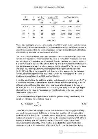
REAL GAS FLOW: GAS WELL TESTING                              269


                                                                                   2
                               Q          t     n  Q j     ∆ mp        2 n     psia /cp/(Mscf/d)
                                                               () FQ−
                                                j1 Q
                             Mscf/d     hrs         n  t ∆  j   Q n         .03     .035      .04
                                                =
                                                  hrs         F = .047
                            10 × 10 3    12        12          3263        3433     3383     3333

                            20     "     24        18          3260        3600     3500     3400

                            30     "     36        24          3268        3778     3628     3478

                            40     "     48        30          3271        3951     3751     3551
                                                          TABLE 8.4

                     These data points plot almost as a horizontal straight line which implies an infinite area.
                     This is to be expected since the value of F determined in the first part of this exercise is
                     under the assumption that the reservoir pressure remains constant throughout the test,
                     which implicitly assumes that the reservoir is infinite.

                     The correct plot should have some positive slope corresponding to the fact that a finite
                     volume is being drained. This means that the value of F should be decreased on a trial
                     and error basis until a straight line is obtained. The plot has been re-drawn for values of
                     F of 0.040, 0.035 and 0.030, refer table 8.4 and fig. 8.10. For the latter two values there
                     is a slight degree of upward curvature, whereas for the value of F = .04 the plot is linear
                                        2
                     with slope 12.2 psia /cp/Mscf/d/hr, which implies that the pore volume drained is
                              6
                     35.5 × 10  cu ft. Using the values of h = 40 ft and φ  = .2 as average for the drainage
                     volume, the area is approximately 100 acres. Further, the intercept gives the value of
                                                            2
                     the Darcy flow coefficient B as 3186 psia /cp/(Mscf/d).
                     It must be admitted that the stabilized analysis technique using the plot of equ. (8.47) is
                     a precarious business, to say the least. In this exercise any of the plots in fig. 8.10, for
                     different values of F, could be taken to be linear leading to estimates of the area of
                     60 acres, for F = .035, or 43 acres for F = .030. In a great many cases the high degree
                     of sensitivity to the value of F precludes any reliable estimate of the pore volume or
                     area drained being made.

                     To summarize the foregoing remarks on stabilized gas well testing; semi-steady flow
                     conditions will occur for some fixed value of

                                              kt
                           t DA  = 0.000264                                                         (8.36)
                                            ( ) cA
                                          φµ
                                                i
                     Therefore, such tests will be appropriate in reservoirs which have a high permeability
                     and small drainage area so that the semi-steady state condition will be reached in a
                     relatively short period of time. The reader should be cautioned, however, that these are
                     not the sole criteria. In exercise 8.1, for instance, the actual permeability is 100 mD and
                     the well is draining from the centre of a square of area 100 acres. Under these
                     circumstances the value of t DA which must be exceeded before semi-steady state
                     conditions prevail is 0.1 (refer either MBH charts, fig. 7.11, or the Dietz chart fig.6.4).