
Page 109 - Fundamentals of Water Treatment Unit Processes : Physical, Chemical, and Biological
P. 109
64 Fundamentals of Water Treatment Unit Processes: Physical, Chemical, and Biological
4.3.3.3.2 General Applicability of Equation 4.9 clearly that the solute concentration within the reactor varies
First, consider that we may wish to let either Q or C 0 , or both with Z. Therefore, the reactor is not homogeneous. Conse-
at once, vary with time, which is the operating condition for quently, the materials balance equation cannot be applied to
most treatment plants. Such a condition can be imposed the reactor as a whole, that is, over the column length. The
merely by writing Equation 4.9 in finite difference form and condition of homogeneity may be true, however, if the vol-
solving numerically. ume element is infinitesimal. Figure 4.6 shows such a volume
In addition, we can impose any special conditions (as noted element for a column slice of thickness DZ.As DZ approaches
in Section 4.3.3.1) that we wish, such as for a ‘‘batch’’ reactor, zero, then the solute approaches homogeneity within the
that is, Q C in ¼ 0 and Q C ¼ 0. Or we can impose the ‘‘steady element. Thus, the materials balance equation may be applied
state’’ condition, in which the observed mass rate of change in to the infinitesimal slice.
the reactor, the term on the left side of Equation 4.9, is zero.
4.3.3.3.5 Application of Materials Balance Equation
Finally, we can let the rate of reaction equal zero and solve for
the effluent concentration, C, leaving the reactor, such as for a Figure 4.7 shows a materials balance for an infinitesimal
salt solution displacing some other solution from the reactor. column slice of thickness, DZ and area, A. The corresponding
mathematical statement is given by Equation 4.10. The mass
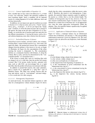
4.3.3.3.3 Packed-Bed Reactor (Column) transport terms are advection and dispersion, both illustrated
Packed-bed reactors include: activated carbon, ion exchange, in Figure 4.7.
trickling filters, various biofilm reactors (e.g., slow sand), and
rapid rate filters. All packed-bed reactors have concentration q(C DZ A) ¼ v A C in v A C out þ j A j A
changes from the entrance of the reactor to its exit, as Figure qt 0 in out
4.6 illustrates. In Figure 4.6, the concentration of the solute q(C DZ A)
entering the reactor is designated, C 0 . The concentration qt r (4:10)
declines as a continuous function with distance, Z, along the
column, that is, C(Z) t , and may be characterized as the ‘‘con- in which
centration profile’’ at a designated time, t. Z is the distance along column from entrance (m)
If the reactor is steady state, such as a trickling filter with v is the velocity within column (m=s)
no change in Q or C 0 with time, then the profile will remain A is the cross-sectional area of column (m )
2
constant. But if the porous media becomes saturated with t is the elapsed time from beginning of operation (s)
time, such as with GAC, an ion-exchange bed, or a rapid
C in is the concentration of given contaminant into the
rate filter, then the profile will advance downstream with time. 3
infinitesimal slice (kg=m )
In addition to packed-bed reactors, this same schematic,
C out is the concentration of given contaminant leaving the
that is, Figure 4.6, is applicable to a ‘‘plug flow’’ type of 3
infinitesimal slice (kg=m )
fluidized reactor. The latter may include reactors that are 2
j in is the dispersion flux density into element (kg=m =s)
long and narrow, such as ‘‘conventional’’ activated sludge.
j out is the dispersion flux density leaving element
A river would also fit in this category. 2
(kg=m =s)
4.3.3.3.4 Homogeneity Requirement
As noted previously, the materials balance equation is valid
Convection in Dispersion in
only for a homogeneous volume element. Figure 4.6 shows –
– ∂(vC) ΔZ ∂j ΔZ
vC– A + j – A
∂Z 2 ∂Z 2
C
0 C 0
Z
–
vCA + jA
ΔZ
2
Z ΔZ ∂C ΔZA
∂t r
ΔZ Reaction
Column length ΔZ C(Z) t
2
–
– ∂(vC) ΔZ ∂j ΔZ
vC– A + j– A
∂Z 2 ∂Z 2
Convection out Dispersion out
Inflection point
FIGURE 4.7 Materials balance on infinitesimal column slice of
thickness, DZ, and area, A showing terms for derivation of materials
FIGURE 4.6 Concentration profile in a packed-bed reactor. balance equation.