
Page 111 - Fundamentals of Water Treatment Unit Processes : Physical, Chemical, and Biological
P. 111
66 Fundamentals of Water Treatment Unit Processes: Physical, Chemical, and Biological
∂(C·V) ∂(C·V)
∂t ∂t
obs obs
Reactor Reactor
Q·C in Q·C
∂(C·V) = ∂(C·V)
∂t ∂t
r r
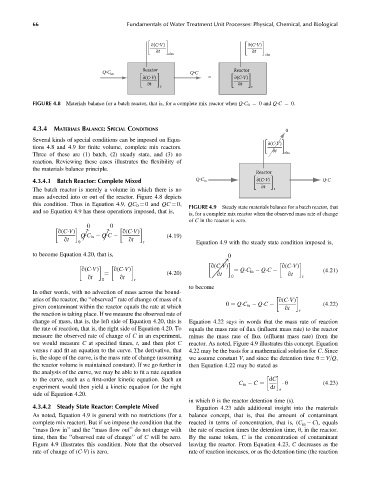
FIGURE 4.8 Materials balance for a batch reactor, that is, for a complete mix reactor when Q C 0 ¼ 0 and Q C ¼ 0.
4.3.4 MATERIALS BALANCE:SPECIAL CONDITIONS 0
Several kinds of special conditions can be imposed on Equa-
∂(C·V)
tions 4.8 and 4.9 for finite volume, complete mix reactors.
∂t
Three of these are (1) batch, (2) steady state, and (3) no obs
reaction. Reviewing these cases illustrates the flexibility of
the materials balance principle.
Reactor
4.3.4.1 Batch Reactor: Complete Mixed Q·C in ∂(C·V) Q·C
∂t
The batch reactor is merely a volume in which there is no r
mass advected into or out of the reactor. Figure 4.8 depicts
this condition. Thus in Equation 4.9, QC 0 ¼ 0 and QC ¼ 0,
FIGURE 4.9 Steady state materials balance for a batch reactor, that
and so Equation 4.9 has these operations imposed, that is,
is, for a complete mix reactor when the observed mass rate of change
of C in the reactor is zero.
0 0
q(C V) ! ! q(C V)
qt Q C in Q C qt (4:19)
0 r Equation 4.9 with the steady state condition imposed is,
to become Equation 4.20, that is, 0
q(C V) q(C V)
q(C V) q(C V) ! (4:21)
(4:20) qt ¼ Q C in Q C qt
qt qt 0 r
¼
0 r
to become
In other words, with no advection of mass across the bound-
aries of the reactor, the ‘‘observed’’ rate of change of mass of a q(C V)
given contaminant within the reactor equals the rate at which 0 ¼ Q C in Q C qt r (4:22)
the reaction is taking place. If we measure the observed rate of
change of mass, that is, the left side of Equation 4.20, this is Equation 4.22 says in words that the mass rate of reaction
the rate of reaction, that is, the right side of Equation 4.20. To equals the mass rate of flux (influent mass rate) to the reactor
measure the observed rate of change of C in an experiment, minus the mass rate of flux (effluent mass rate) from the
we would measure C at specified times, t, and then plot C reactor. As noted, Figure 4.9 illustrates this concept. Equation
versus t and fit an equation to the curve. The derivative, that 4.22 may be the basis for a mathematical solution for C. Since
is, the slope of the curve, is the mass rate of change (assuming we assume constant V, and since the detention time u ¼ V=Q,
the reactor volume is maintained constant). If we go further in then Equation 4.22 may be stated as
the analysis of the curve, we may be able to fit a rate equation
to the curve, such as a first-order kinetic equation. Such an dC
u (4:23)
C in C ¼
experiment would then yield a kinetic equation for the right dt
r
side of Equation 4.20.
in which u is the reactor detention time (s).
4.3.4.2 Steady State Reactor: Complete Mixed Equation 4.23 adds additional insight into the materials
As noted, Equation 4.9 is general with no restrictions (for a balance concept, that is, that the amount of contaminant
complete mix reactor). But if we impose the condition that the reacted in terms of concentration, that is, (C in C), equals
‘‘mass flow in’’ and the ‘‘mass flow out’’ do not change with the rate of reaction times the detention time, u, in the reactor.
time, then the ‘‘observed rate of change’’ of C will be zero. By the same token, C is the concentration of contaminant
Figure 4.9 illustrates this condition. Note that the observed leaving the reactor. From Equation 4.23, C decreases as the
rate of change of (C V) is zero. rate of reaction increases, or as the detention time (the reaction