
Page 205 - Geothermal Energy Renewable Energy and The Environment
P. 205
192 Geothermal Energy: Renewable Energy and the Environment
10,000
Lht. dry Hvy. damp Various rock
soil soil
Hvy. dry Hvy. sat.
soil soil
Horizontal
Soil T = 8.9°C
heating Loops
Length (m) 1000 Soil T = 11.1°C
Soil T = 24.4°C
Horizontal Soil T = 21.1°C
cooling Loops
100
0 0.5 1.0 1. 5 2 .0 2. 5 3 .0 3.5
Soil Thermal Conductivity (W/m-°K)
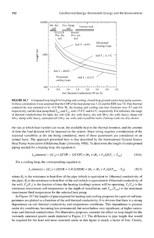
FIGUre 10.7 Computed loop length for heating and cooling, closed-loop ground source heat pump systems.
In these calculations it was assumed that the COP of the heat pump was 3.24 and the EER was 7.8. Pipe thermal
conductivity was assumed to be 14.8 W/m-°K, the heating and cooling run time fractions were 0.5 and 0.6
respectively, and the heat pump fluid T max and T min were 37.8°C and 4.4°C, respectively. For reference, the range
of thermal conductivities for light, dry soil (Lht. dry soil); heavy, dry soil (Hvy. dry soil); heavy, damp soil
(Hvy. damp soil); heavy, saturated soil (Hvy. sat. soil); and crystalline rocks (Various rock) are also shown.
the rate at which heat transfer can occur, the available heat in the thermal resource, and the amount
of time the load demand will be imposed on the system. Since sizing requires consideration of the
seasonal variability at the site being considered, most of these parameters are considered on an
annual basis. The approach presented here is that described by the International Ground Source
Heat Pump Association (Oklahoma State University 1988). To determine the length of underground
piping needed for a heating loop, the equation is
L (meters) = {(C ) × [(COP − 1)/COP] × [R + (R × F )]}/(T − T ) (10.4).
P
H
min
S
H
L
H
For a cooling loop, the corresponding equation is
L (meters) = {(C ) × [(EER + 3.412)/EER] × [R + (R × F )]}/(T max − T ), (10.5)
C
P
H
S
C
C
where R is the resistance to heat flow of the pipe (which is equivalent to 1/thermal conductivity of
P
the pipe), R is the resistance to heat flow of the soil (which is equivalent to 1/thermal conductivity of
S
the soil), F (F ) is the fraction of time the heating (cooling) system will be operating, T (T ) is the
L
H
H
C
minimum (maximum) soil temperature at the depth of installation, and T (T max ) is the minimum
min
(maximum) fluid temperature for the selected heat pump.
In Figure 10.7 the lengths of pipe required for heating and cooling purposes for a pair of soil tem-
peratures are plotted as a function of the soil thermal conductivity. It is obvious that there is a strong
dependence on soil thermal conductivity and temperature conditions. This dependence is greatest
under dry conditions, becoming less pronounced, but nevertheless very significant, at higher satura-
tions and thermal conductivities. For illustrative purposes, consider the effect on loop length for the
variously saturated quartz sands depicted in Figure 2.3. The difference in pipe length that would
be required for the least and most saturated sands in that figure is nearly a factor of four. Clearly,