
Page 70 - Geothermal Energy Renewable Energy and The Environment
P. 70
54 Geothermal Energy: Renewable Energy and the Environment
of the orifice between interconnected pores, and the viscosity of the fluid. In Figure 4.3B, the size of
the orifices between pores is consistently much greater along flow path a than along flow path to b,
resulting in a preferential fluid flow path in the vertical direction. It is this type of porosity feature
that results in observable flow anisotropy in intact (i.e., no fractures) rocks.
definiTion of maTrix permeabiliTy
The quantitative description of fluid flow in porous media was formalized by Henry Darcy in the
mid-1800s:
q = − (κ/μ) × A × ∇(P), (4.1)
2
3
where q is the flux (m /m /s), κ is the permeability (in units of area, m ), A is the cross-sectional
2
2
area (m ), μ is the dynamic viscosity (kg/(m-s)) and ∇(P) is the gradient in pressure, including that
due to gravity (i.e., the specific weight of water). Strictly, this law only applies to very slow flow of
a single, homogeneous phase. It is often used as an approximation for more complex conditions, but
its limitations need to be recognized. Non-Darcy flow, which is realized under conditions where
fluid velocities are high, is commonly encountered in situations involving pumping of wells for
geothermal applications.
Permeability is a fundamental concept that underlies most considerations in which the flow of
fluid in the subsurface is important. Consider, again, the various flow paths in Figure 4.3. In A,
despite the high porosity of the sample, fluid cannot pass through the material. The resulting flux
(q, Equation 4.1) will therefore be zero, which also requires that the permeability (κ in Equation 4.1)
be zero. In B, flow can exit the sample in two locations, via paths a and b. Path a provides the most
direct path and the least restrictive (i.e., widest) pore throats and the flux exiting via that route will
be greater than that exiting the block via path b, even when the two paths available at b are consid-
ered. Path a must therefore have a greater permeability, κ, than path b.
The discrepancy between permeability values along the different paths in B demonstrates an
important aspect regarding permeability. First, permeability is often scale dependent. Given that
pores in rocks are often in the submillimeter size range, clearly the depiction in Figure 4.3 represents
a very small piece of rock. If the depicted sample had been obtained from a much larger rock in which
there was a random distribution of pore characteristics, it is possible the permeability measured for
the larger sample would average out the effects of paths such as a and b and the resulting value for κ
would be different from that obtained for either path individually. Second, the depiction in B dem-
onstrates that permeability can be directionally heterogeneous. For instances in which it would be
important to maximize the fluid flow volume it is important to understand what the local permeability
heterogeneity is in order to assure that a borehole accesses the most favorable permeability field.
The units of permeability, κ, reflect the means whereby it is measured in the laboratory. The most
common unit used for permeability is the darcy. One darcy is defined as the volumetric flow rate
3
of 1 cm /s of a fluid with a viscosity of 1 centipoise through a cross-sectional area of 1 cm under a
2
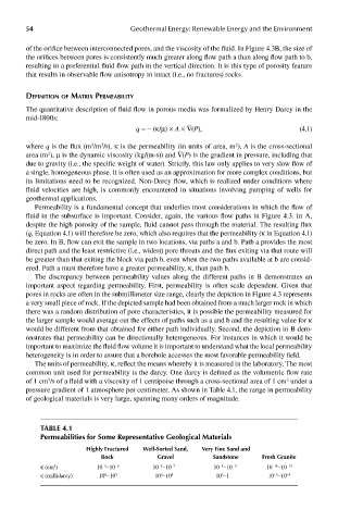
pressure gradient of 1 atmosphere per centimeter. As shown in Table 4.1, the range in permeability
of geological materials is very large, spanning many orders of magnitude.
Table 4.1
permeabilities for some representative Geological materials
highly Fractured well-sorted sand, Very Fine sand and
rock Gravel sandstone Fresh Granite
−14
−8
2
−5
κ (cm ) 10 −10 −6 10 −10 −7 10 −10 −11 10 −10 −15
−3
−3
8
κ (millidarcy) 10 −10 5 10 −10 4 10 −1 10 −10 −4
3
6