
Page 75 - Geothermal Energy Renewable Energy and The Environment
P. 75
Subsurface Fluid Flow: The Hydrology of Geothermal Systems 59
10 –7
Fracture spacing
10 –8 1 cm
10 cm Highly fractured rock
10 –9 100 cm
1000 cm Gravel
10 –10
Permeability (m 2 ) 10 –11 Fracture width
–12
10
0.1 cm
10 –13 0.001 cm
Fine sand
10 –14
0.01 cm
10 –15
10 –16
10 –5 10 –4 10 –3 10 –2 10 –1 1 10 10 2
Porosity (percent)
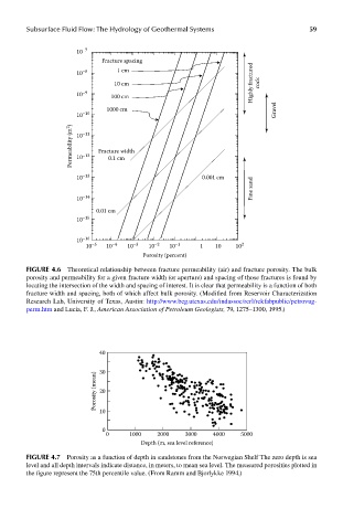
FIGUre 4.6 Theoretical relationship between fracture permeability (air) and fracture porosity. The bulk
porosity and permeability for a given fracture width (or aperture) and spacing of those fractures is found by
locating the intersection of the width and spacing of interest. It is clear that permeability is a function of both
fracture width and spacing, both of which affect bulk porosity. (Modified from Reservoir Characterization
Research Lab, University of Texas, Austin: http://www.beg.utexas.edu/indassoc/rcrl/rckfabpublic/petrovug-
perm.htm and Lucia, F. J., American Association of Petroleum Geologists, 79, 1275–1300, 1995.)
40
30
Porosity (mean) 20
10
0
0 1000 2000 3000 4000 5000
Depth (m, sea level reference)
FIGUre 4.7 Porosity as a function of depth in sandstones from the Norwegian Shelf The zero depth is sea
level and all depth intervals indicate distance, in meters, to mean sea level. The measured porosities plotted in
the figure represent the 75th percentile value. (From Ramm and Bjorlykke 1994.)