
Page 72 - Geothermal Energy Renewable Energy and The Environment
P. 72
56 Geothermal Energy: Renewable Energy and the Environment
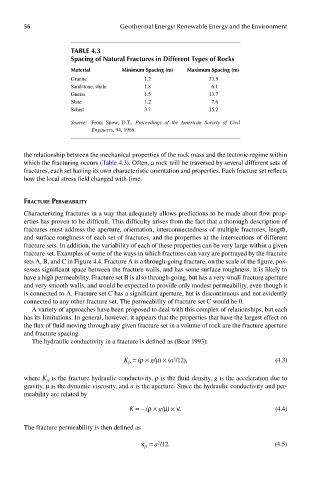
Table 4.3
spacing of natural Fractures in different Types of rocks
material minimum spacing (m) maximum spacing (m)
Granite 1.2 33.5
Sandstone, shale 1.8 6.1
Gneiss 1.5 13.7
Slate 1.2 7.6
Schist 3.7 15.2
Source: From Snow, D.T., Proceedings of the American Society of Civil
Engineers, 94, 1968.
the relationship between the mechanical properties of the rock mass and the tectonic regime within
which the fracturing occurs (Table 4.3). Often, a rock will be traversed by several different sets of
fractures, each set having its own characteristic orientation and properties. Each fracture set reflects
how the local stress field changed with time.
fracTure permeabiliTy
Characterizing fractures in a way that adequately allows predictions to be made about flow prop-
erties has proven to be difficult. This difficulty arises from the fact that a thorough description of
fractures must address the aperture, orientation, interconnectedness of multiple fractures, length,
and surface roughness of each set of fractures, and the properties at the intersections of different
fracture sets. In addition, the variability of each of these properties can be very large within a given
fracture set. Examples of some of the ways in which fractures can vary are portrayed by the fracture
sets A, B, and C in Figure 4.4. Fracture A is a through-going fracture, on the scale of the figure, pos-
sesses significant space between the fracture walls, and has some surface roughness. It is likely to
have a high permeability. Fracture set B is also through-going, but has a very small fracture aperture
and very smooth walls, and would be expected to provide only modest permeability, even though it
is connected to A. Fracture set C has a significant aperture, but is discontinuous and not evidently
connected to any other fracture set. The permeability of fracture set C would be 0.
A variety of approaches have been proposed to deal with this complex of relationships, but each
has its limitations. In general, however, it appears that the properties that have the largest effect on
the flux of fluid moving through any given fracture set in a volume of rock are the fracture aperture
and fracture spacing.
The hydraulic conductivity in a fracture is defined as (Bear 1993):
K = (ρ × g/μ) × (a /12), (4.3)
2
fr
where K is the fracture hydraulic conductivity, ρ is the fluid density, g is the acceleration due to
fr
gravity, μ is the dynamic viscosity, and a is the aperture. Since the hydraulic conductivity and per-
meability are related by
K = − (ρ × g/μ) × κ. (4.4)
The fracture permeability is then defined as
κ = a /12. (4.5)
2
fr