
Page 72 - Handbook of Battery Materials
P. 72
38 2 Practical Batteries
Discharge end voltage/V vs. Ni(OH) 2 /NiO(OH) -0.8 1 2 3 4 5 6 7
-1.0
-1.2
-1.4
2000
1000
0
Cycle number 3000
Hydrogen absorbing alloy : 1 LaNi , 2 LaNi Co,
5
4
3 LaNi 3 Co 2 , 4 LaNi 2 Co 3 , 5 La 0.8 Ce 0.2 Ni 2 Co 3 ,
6 La 0.8 Nd 0.2 Ni 2 Co 3 , 7 MmNi 2 Co 3
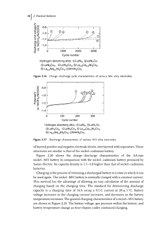
Figure 2.16 Charge–discharge cycle characteristics of various MH alloy electrodes.
Potential/V vs. Ni(OH) 2 /NiO(OH) -0.8 7 5 6 4 3 2 1
-1.0
-1.2
-1.4
0 100 200 300
Cycle number
Hydrogen absorbing alloy : 1 LaNi 5 , 2 LaNi 4 Co,
3 LaNi 3 Co 2 , 4 LaNi 2 Co 3 , 5 La 0.8 Ce 0.2 Ni 2 Co 3 ,
6 La 0.8 Nd 0.2 Ni 2 Co 3 , 7 MmNi 2 Co 3
Figure 2.17 Discharge characteristics of various MH alloy electrodes.
of layered positive and negative electrode sheets, interlayered with separators. These
structures are similar to that of the nickel–cadmium battery.
Figure 2.20 shows the charge–discharge characteristics of the AA-size
nickel–MH battery in comparison with the nickel–cadmium battery produced by
Sanyo Electric. Its capacity density is 1.5–1.8 higher than that of nickel–cadmium
batteries.
Charging is the process of returning a discharged battery to a state in which it can
be used again. The nickel–MH battery is normally charged with a constant current.
This method has the advantage of allowing an easy calculation of the amount of
charging based on the charging time. The standard for determining discharge
◦
capacity is a charging time of 16 h using a 0.1 C current at 20 ± 5 C. Battery
voltage increases as the charging current increases, and decreases as the battery
temperature increases. The general charging characteristics of a nickel–MH battery
are shown in Figure 2.21. The battery voltage, gas pressure within the battery, and
battery temperature change as time elapses under continued charging.