
Page 132 - Handbook of Electrical Engineering
P. 132
114 HANDBOOK OF ELECTRICAL ENGINEERING
The input power factor PF in of the stator current is:-
P in1 94.971
PF in = = = 0.4828 pu lagging
S in1 196.699
The efficiency η of the motor at starting is zero.
The starting torque T e1 is:-
2 2
3 R 2 V m 3 × 0.253 × 111.994
T e1 = = = 54431.0nm
2 2 2 2
R 2 + X 2 0.253 + 0.333
which is 2.417 times the full-load value.
5.2.6 Typical Impedance Data for two-Pole and four-Pole Induction Motors
Tables 5.1–5.4 show the approximate resistance and reactance values in per-unit for two-pole and
four-pole low voltage induction motors that are generally of the Design D type. Tables 5.5–5.8 show
the approximate resistance and reactance values in per-unit for two-pole and four-pole high voltage
induction motors that are of the reduced starting current type. In the absence of exact data from a
manufacturer these data can be used for system studies such as starting motors, transient stability and
fault current contribution. The data from a manufacturer should be used for calculations and system
studies that are to be carried out during the detailed design phase of a project.
5.2.7 Representing the Deep-Bar Effect by Two Parallel Branches
Consider a series connection of resistance and inductive reactance, denoted as R n + jX . Any number,
n
n, of these branches can be connected in parallel. The sum of these parallel branches can also be
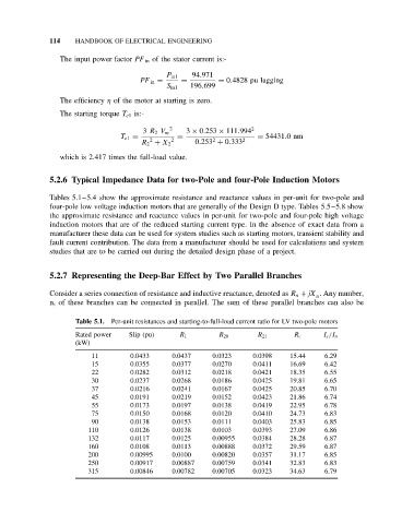
Table 5.1. Per-unit resistances and starting-to-full-load current ratio for LV two-pole motors
Rated power Slip (pu) R 1 R 20 R 21 R c I s /I n
(kW)
11 0.0433 0.0437 0.0323 0.0398 15.44 6.29
15 0.0355 0.0377 0.0270 0.0411 16.69 6.42
22 0.0282 0.0312 0.0218 0.0421 18.35 6.55
30 0.0237 0.0268 0.0186 0.0425 19.81 6.65
37 0.0216 0.0241 0.0167 0.0425 20.85 6.70
45 0.0191 0.0219 0.0152 0.0423 21.86 6.74
55 0.0173 0.0197 0.0138 0.0419 22.95 6.78
75 0.0150 0.0168 0.0120 0.0410 24.73 6.83
90 0.0138 0.0153 0.0111 0.0403 25.83 6.85
110 0.0126 0.0138 0.0103 0.0393 27.09 6.86
132 0.0117 0.0125 0.00955 0.0384 28.28 6.87
160 0.0108 0.0113 0.00888 0.0372 29.59 6.87
200 0.00995 0.0100 0.00820 0.0357 31.17 6.85
250 0.00917 0.00887 0.00759 0.0341 32.83 6.83
315 0.00846 0.00782 0.00705 0.0323 34.63 6.79