
Page 309 - Handbook of Materials Failure Analysis
P. 309
6 Results and Discussion 305
Buttering
Weld
Ferrite Austenite
Ferrite-buttering Buttering-weld
(a) interface interface
Ferrite Weld Austenite
(b) Crack Buttering
FIGURE 12.20
(a) Schematic representation of crack at two different interfaces of the dissimilar metal
welded joint, (b) FE mesh of the SEB specimen with different material properties at different
regions and initial crack at the ferrite-buttering interface.
14,000
s2 s3 s4 s5 Exp.
12,000 s1 s6 s7 Analysis
s8
10,000
Load (N) 8000
6000
4000
2000
0
0 1 2 3 4 5
CMOD (mm)
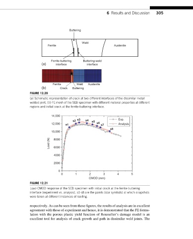
FIGURE 12.21
Load-CMOD response of the SEB specimen with initial crack at the ferrite-buttering
interface (experiment vs. analysis). s1-s8 are the points (star symbols) at which snapshots
were taken at different instances of loading.
respectively. As can be seen from these figures, the results of analysis are in excellent
agreement with those of experiment and hence, it is demonstrated that the FE formu-
lation with the porous plastic yield function of Rousselier’s damage model is an
excellent tool for analysis of crack growth and path in dissimilar weld joints. The