
Page 127 - Handbook of Structural Steel Connection Design and Details
P. 127
Design of Connections for Axial, Moment, and Shear Forces
112 Chapter Two
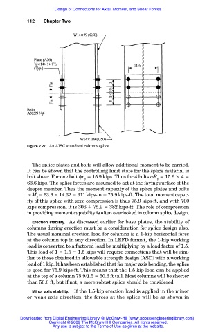
Figure 2.27 An AISC standard column splice.
The splice plates and bolts will allow additional moment to be carried.
It can be shown that the controlling limit state for the splice material is
bolt shear. For one bolt r 15.9 kips. Thus for 4 bolts R 15.9 4
v v
63.6 kips. The splice forces are assumed to act at the faying surface of the
deeper member. Thus the moment capacity of the splice plates and bolts
is M 63.6 14.32 911 kips-in 75.9 kips-ft. The total moment capac-
s
ity of this splice with zero compression is thus 75.9 kips-ft, and with 700
kips compression, it is 306 75.9 382 kips-ft. The role of compression
in providing moment capability is often overlooked in column splice design.
Erection stability. As discussed earlier for base plates, the stability of
columns during erection must be a consideration for splice design also.
The usual nominal erection load for columns is a 1-kip horizontal force
at the column top in any direction. In LRFD format, the 1-kip working
load is converted to a factored load by multiplying by a load factor of 1.5.
This load of 1 1.5 1.5 kips will require connections that will be sim-
ilar to those obtained in allowable strength design (ASD) with a working
load of 1 kip. It has been established that for major axis bending, the splice
is good for 75.9 kips-ft. This means that the 1.5 kip load can be applied
at the top of a column 75.9/1.5 50.6 ft tall. Most columns will be shorter
than 50.6 ft, but if not, a more robust splice should be considered.
Minor axis stability. If the 1.5-kip erection load is applied in the minor
or weak axis direction, the forces at the splice will be as shown in
Downloaded from Digital Engineering Library @ McGraw-Hill (www.accessengineeringlibrary.com)
Copyright © 2009 The McGraw-Hill Companies. All rights reserved.
Any use is subject to the Terms of Use as given at the website.