
Page 128 - Handbook of Structural Steel Connection Design and Details
P. 128
Design of Connections for Axial, Moment, and Shear Forces
Design of Connections for Axial, Moment, and Shear Forces 113
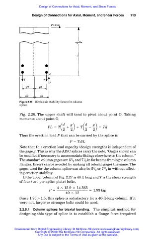
Figure 2.28 Weak-axis stability forces for column
splice.
Fig. 2.28. The upper shaft will tend to pivot about point O. Taking
moments about point O,
d g d g
PL 5 Ta 1 b 1 Ta 2 b 5 Td
2 2 2 2
Thus the erection load P that can be carried by the splice is
P Td/L
Note that this erection load capacity (design strength) is independent of
the gage g. This is why the AISC splices carry the note, “Gages shown can
be modified if necessary to accommodate fittings elsewhere on the column.”
1
1
The standard column gages are 5 / and 7 / in for beams framing to column
2
2
flanges. Errors can be avoided by making all column gages the same. The
1
1
gages used for the column splice can also be 5 / or 7 / in without affect-
2
2
ing erection stability.
If the upper column of Fig. 2.27 is 40 ft long and T is the shear strength
of four (two per splice plate) bolts,
4 3 15.9 3 14.565
P 5 5 1.93 kip
40 3 12
Since 1.93 > 1.5, this splice is satisfactory for a 40-ft-long column. If it
were not, larger or stronger bolts could be used.
2.2.5.1 Column splices for biaxial bending. The simplest method for
designing this type of splice is to establish a flange force (required
Downloaded from Digital Engineering Library @ McGraw-Hill (www.accessengineeringlibrary.com)
Copyright © 2009 The McGraw-Hill Companies. All rights reserved.
Any use is subject to the Terms of Use as given at the website.