
Page 129 - Handbook of Structural Steel Connection Design and Details
P. 129
Design of Connections for Axial, Moment, and Shear Forces
114 Chapter Two
strength) that is statically equivalent to the applied moments and then
to design the bolts, welds, plates, and fillers (if required) for this force.
Major axis bending. If M is the major axis applied moment and d is the
x
depth of the deeper of the two columns, the flange force (or required
strength) is
M x
F 5
fx
d
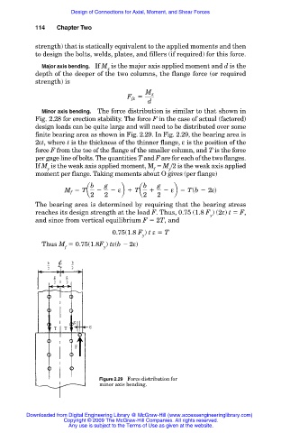
Minor axis bending. The force distribution is similar to that shown in
Fig. 2.28 for erection stability. The force F in the case of actual (factored)
design loads can be quite large and will need to be distributed over some
finite bearing area as shown in Fig. 2.29. In Fig. 2.29, the bearing area is
2εt, where t is the thickness of the thinner flange, ε is the position of the
force F from the toe of the flange of the smaller column, and T is the force
per gage line of bolts. The quantities T and F are for each of the two flanges.
If M is the weak axis applied moment, M M /2 is the weak axis applied
y f y
moment per flange. Taking moments about O gives (per flange)
b g b g
5 Ta 2 2 εb 1 Ta 1 2 εb 5 Tsb 2 2εd
M f
2 2 2 2
The bearing area is determined by requiring that the bearing stress
reaches its design strength at the load F. Thus, 0.75 (1.8 F ) (2ε) t F,
y
and since from vertical equilibrium F 2T, and
0.75(1.8 F ) t ε T
y
Thus M 0.75(1.8F ) tε(b 2ε)
f y
Figure 2.29 Force distribution for
minor axis bending.
Downloaded from Digital Engineering Library @ McGraw-Hill (www.accessengineeringlibrary.com)
Copyright © 2009 The McGraw-Hill Companies. All rights reserved.
Any use is subject to the Terms of Use as given at the website.