Page 131 - Handbook of Structural Steel Connection Design and Details
P. 131

Design of Connections for Axial, Moment, and Shear Forces

                    116    Chapter Two


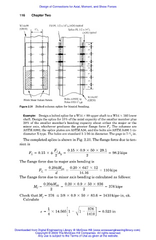
                    Figure 2.31 Bolted column splice for biaxial bending.

                      Example: Design a bolted splice for a W14   99 upper shaft to a W14   193 lower
                      shaft. Design the splice for 15% of the axial capacity of the smaller member plus
                      20% of the smaller member’s bending capacity about either the major or the
                      minor axis, whichever produces the greater flange force F . The columns are
                                                                      f
                      ASTM A992, the splice plates are ASTM A36, and the bolts are ASTM A490 1-in-
                                                                                 1
                      diameter X type. The holes are standard 1-1/16-in diameter. The gage is 7- / in.
                                                                                  2
                      The completed splice is shown in Fig. 2.31. The flange force due to ten-
                    sion is
                                       Fy      0.15 3 0.9 3 50 3 29.1
                            5 0.15 3      A g 5                      5 98.2 kips
                         F f t
                                        2                2
                    The flange force due to major axis bending is
                                                0.20 3 647 3 12
                                    0.20 M px
                               F 5            5                 5 110 kips
                                        d            14.16
                                f x
                    The flange force due to minor axis bending is calculated as follows:
                                 0.20 M  py  0.20 3 0.9 3 50 3 836
                            M 5            5                       5 376 kips
                              f
                                     2                 2
                    Check that M   376 # 3/8 3 0.9 3 50 3 83.6 5 1410 kips-in, ok .
                                 f
                      Calculate
                                    1                     376
                                e 5   3 14.565c1 2   1 2      d 5 0.523  in
                                    4              B     1410


                 Downloaded from Digital Engineering Library @ McGraw-Hill (www.accessengineeringlibrary.com)
                             Copyright © 2009 The McGraw-Hill Companies. All rights reserved.
                              Any use is subject to the Terms of Use as given at the website.
   126   127   128   129   130   131   132   133   134   135   136