
Page 130 - Handbook of Structural Steel Connection Design and Details
P. 130
Design of Connections for Axial, Moment, and Shear Forces
Design of Connections for Axial, Moment, and Shear Forces 115
and solving for ε
1 1 b 2 40 Mf 1 8 Mf
e 5 b 2 a b 2 a b 5 bc1 2 1 2 d
4 2B 2 27 F y 4 B 3 M py
1 2
where M py 5 F Z 5 F y tb
y y
2
This expression for ε is valid as long as
27 F tb 2 3
y
# a
M f b 5 M py
40 4 8
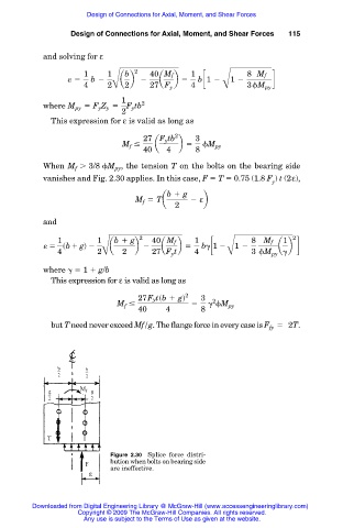
When M . 3/8 M , the tension T on the bolts on the bearing side
py
f
vanishes and Fig. 2.30 applies. In this case, F T 0.75 (1.8 F ) t (2ε),
y
b 1 g
M f 5 Ta 2 εb
2
and
1 1 b 1 g 2 40 Mf 1 8 Mf 1 2
e 5 sb1 gd 2 a b 2 a b 5 b c1 2 1 2 a b d
4 2B 2 27 F y t 4 B 3 M py
where 1 g/b
This expression for ε is valid as long as
27Fytsb 1 gd 2 3
2
M # 5 M py
f
40 4 8
but T need never exceed Mf/g. The flange force in every case is F 5 2T.
fy
Figure 2.30 Splice force distri-
bution when bolts on bearing side
are ineffective.
Downloaded from Digital Engineering Library @ McGraw-Hill (www.accessengineeringlibrary.com)
Copyright © 2009 The McGraw-Hill Companies. All rights reserved.
Any use is subject to the Terms of Use as given at the website.