
Page 134 - Handbook of Structural Steel Connection Design and Details
P. 134
Design of Connections for Axial, Moment, and Shear Forces
Design of Connections for Axial, Moment, and Shear Forces 119
In addition to the checks for the bolts and splice plates, the column
sections should also be checked for bearing and block shear rupture.
These are not necessary in this case because t 0.780 > t 0.50,
f p
the edge distances for the column are the same as for the plates, and
the column material is stronger than the plate material.
2.2.5.2 Splices in truss chords. These splices must be designed for 50%
of the chord load as an axial force, or 2% of the chord load as a trans-
verse force, as discussed in Sec. 5.5.3, even if the load is compression and
the members are finished to bear. As discussed earlier, these splices
may be positioned in the center of a truss panel and, therefore, must pro-
vide some degree of continuity to resist bending. For the tension chord,
the splice must be designed to carry the full tensile load.
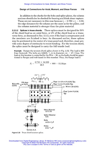
Example Design the tension chord splice shown in Fig. 2.32. The load is 800
7
kips (factored). The bolts are A325X, / in in diameter, r 27.1 kips. The
8 v
load at this location is controlled by the W14 90, so the loads should be appor-
tioned to flanges and web based on this member. Thus, the flange load is
0.710 3 14.520
P f 5 3 800 5 311 kips
26.5
Figure 2.32 Truss chord tension splice.
Downloaded from Digital Engineering Library @ McGraw-Hill (www.accessengineeringlibrary.com)
Copyright © 2009 The McGraw-Hill Companies. All rights reserved.
Any use is subject to the Terms of Use as given at the website.