Page 125 - Handbook of Structural Steel Connection Design and Details
P. 125

Design of Connections for Axial, Moment, and Shear Forces

                    110    Chapter Two


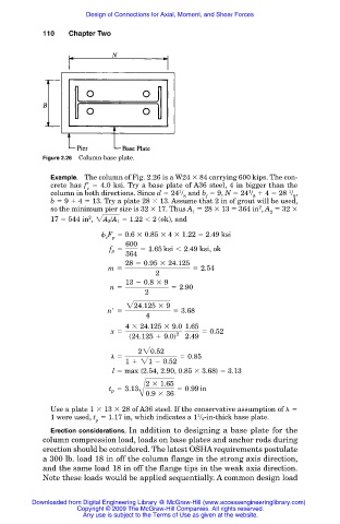
                    Figure 2.26  Column base plate.

                      Example. The column of Fig. 2.26 is a W24   84 carrying 600 kips. The con-
                      crete has f    4.0 ksi. Try a base plate of A36 steel, 4 in bigger than the
                                c
                                                       1
                                                                        1
                                                                                   1
                      column in both directions. Since d   24 / and b   9, N   24 /   4   28  / ,
                                                        8     f           8         8
                      b   9   4   13. Try a plate 28   13. Assume that 2 in of grout will be used,
                                                                           2
                      so the minimum pier size is 32   17. Thus A   28   13   364 in , A   32
                                                          1                   2
                                2
                      17   544 in , 2A 2 /A 1 5 1.22 , 2  (ok), and
                                     F   0.6   0.85   4   1.22   2.49 ksi
                                    c  p
                                         600
                                     f p 5   5 1.65 ksi , 2.49 ksi, ok
                                         364
                                         28 2 0.95 3 24.125
                                     m 5                  5 2.54
                                                 2
                                         13 2 0.8 3 9
                                     n 5             5 2.90
                                              2
                                         224.125 3 9
                                     n  5            5 3.68
                                              4
                                         4 3 24.125 3 9.0 1.65
                                      x 5             2      5 0.52
                                          s24.125 1 9.0d  2.49
                                            220.52
                                     l 5               5 0.85
                                         1 1 21 2 0.52
                                      l   max {2.54, 2.90, 0.85   3.68}   3.13
                                              2 3 1.65
                                     t p 5 3.13       5 0.99 in
                                             B0.9 3 36
                      Use a plate 1   13   28 of A36 steel. If the conservative assumption of
                                                            1
                      1 were used, t   1.17 in, which indicates a 1 / 4-in-thick base plate.
                                  p
                      Erection considerations. In addition to designing a base plate for the
                    column compression load, loads on base plates and anchor rods during
                    erection should be considered. The latest OSHA requirements postulate
                    a 300 lb. load 18 in off the column flange in the strong axis direction,
                    and the same load 18 in off the flange tips in the weak axis direction.
                    Note these loads would be applied sequentially. A common design load


                 Downloaded from Digital Engineering Library @ McGraw-Hill (www.accessengineeringlibrary.com)
                             Copyright © 2009 The McGraw-Hill Companies. All rights reserved.
                              Any use is subject to the Terms of Use as given at the website.
   120   121   122   123   124   125   126   127   128   129   130