
Page 142 - Handbook of Structural Steel Connection Design and Details
P. 142
Design of Connections for Axial, Moment, and Shear Forces
Design of Connections for Axial, Moment, and Shear Forces 127
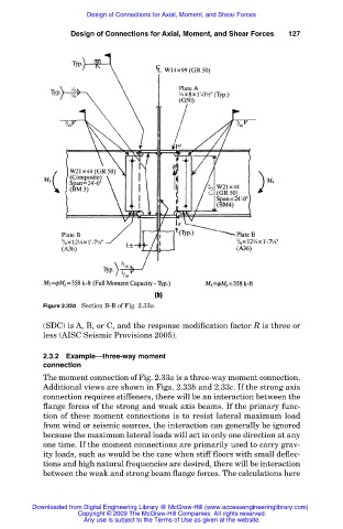
Figure 2.33b Section B-B of Fig. 2.33a.
(SDC) is A, B, or C, and the response modification factor R is three or
less (AISC Seismic Provisions 2005).
2.3.2 Example—three-way moment
connection
The moment connection of Fig. 2.33a is a three-way moment connection.
Additional views are shown in Figs. 2.33b and 2.33c. If the strong axis
connection requires stiffeners, there will be an interaction between the
flange forces of the strong and weak axis beams. If the primary func-
tion of these moment connections is to resist lateral maximum load
from wind or seismic sources, the interaction can generally be ignored
because the maximum lateral loads will act in only one direction at any
one time. If the moment connections are primarily used to carry grav-
ity loads, such as would be the case when stiff floors with small deflec-
tions and high natural frequencies are desired, there will be interaction
between the weak and strong beam flange forces. The calculations here
Downloaded from Digital Engineering Library @ McGraw-Hill (www.accessengineeringlibrary.com)
Copyright © 2009 The McGraw-Hill Companies. All rights reserved.
Any use is subject to the Terms of Use as given at the website.