
Page 143 - Handbook of Structural Steel Connection Design and Details
P. 143
Design of Connections for Axial, Moment, and Shear Forces
128 Chapter Two
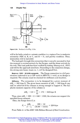
Figure 2.33c Section A-A of Fig. 2.33a.
will be for both a wind or a seismic condition in a region of low to moderate
seismicity (SDC A, B, or C, and R 3), and gravity condition. Thus,
interaction will be included.
The load path through this connection that is usually assumed is that
the moment is carried entirely by the flanges, and the shear entirely by
the web. This load path has been verified by testing (Huang et al., 1973)
and will be the approach used here. Proceeding to the connection design,
the strong axis beam, beam no. 1, will be designed first.
Beam no. 1 W21 62 (A36) composite. The flange connection is a full pen-
etration (referred to as a CJP weld in AWS D1.1) weld, so no design is
required. The column must be checked for stiffeners and doublers.
Stiffeners. The connection is to be designed for a given moment of
M 389 kips-ft. The given beam moment of M 389 kips-ft can
b b
only be achieved if the column is strong enough to support it. The full
plastic moment capacity of the column is
50
M 5 0.9 3 3 173 5 649 kips-ft
p
12
Thus, since M 389 2 649 1300, the column can support the
b
specified beam moment.
Thus, the flange force F is
f
M b 389 3 12
5 5 5 229 kips
F f
d 2 t f s20.99 2 0.615d
From Table 4-1 of the AISC 13th Edition Manual of Steel Construction.
Downloaded from Digital Engineering Library @ McGraw-Hill (www.accessengineeringlibrary.com)
Copyright © 2009 The McGraw-Hill Companies. All rights reserved.
Any use is subject to the Terms of Use as given at the website.