
Page 36 - Handbook of Surface Improvement and Modification
P. 36
2.2 Methods of testing 31
Nano-indenters with a horizontal tip movement capability are frequently used in
1
1
scratch testing. The tips are pyramidal or conical. The pyramidal tip has sharp corners,
1
resulting in significant stress concentration and a complex stress distribution. A conical
1
tip is better due to its circular projection. Considering that the conical tip is small, the
contact stress is extremely high resulting in a rapid failure which makes it difficult to
1
observe transitions in deformation behavior. For this reason, expensive analysis equip-
1
ment is usually required.
A practical methodology was developed and standardized by ASTM (D7027-13) and
1
ISO (19252:2008). The test involves application of a progressive normal load at a con-
stant rate using a 1 mm diameter spherical
tip (simulates the surface scratching with a
1
car key). The geometry of tip permits
more effective examination of scratch
behavior than with pyramid or conical
1
indenters. The results of the test simulate
real-life surface damage at a similar length
1
scale. Because the applied load is known,
the applied stress can be approximated with
finite element methods, providing the cor-
responding mechanistic information of the
1
scratch process. The methodology
employs a variety of microscopy tools for
detailed description of deformation mecha-
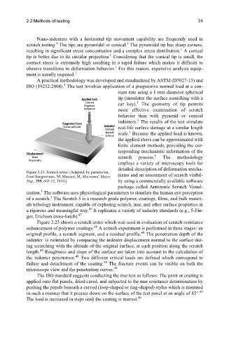
Figure 2.23. Scratch tester. [Adapted, by permission, nisms and an assessment of scratch visibil-
from Sangermano, M; Messori, M, Macromol. Mater.
Eng., 295, 603-12, 2010.] ity using a commercially available software
package called Automatic Scratch Visual-
1
ization. The software uses physiological parameters to simulate the human eye perception
1
of a scratch. The Scratch 5 is a research grade polymer, coatings, films, and bulk materi-
als tribology instrument, capable of exploring scratch, mar, and other surface properties in
47
a rigorous and meaningful way. It replicates a variety of industry standards (e.g., 5-Fin-
47
ger, Erichsen cross-hatch).
Figure 2.23 shows a scratch tester which was used in evaluation of scratch resistance
48
enhancement of polymer coatings. A scratch experiment is performed in three stages: an
48
original profile, a scratch segment, and a residual profile. The penetration depth of the
indenter is estimated by comparing the indenter displacement normal to the surface dur-
ing scratching with the altitude of the original surface, at each position along the scratch
48
length. Roughness and slope of the surface are taken into account in the calculation of
48
the indenter penetration. Two different critical loads are defined which correspond to
48
failure and detachment of the coating. The fracture events can be visible on both the
48
microscope view and the penetration curves.
The ISO standard suggests conducting the mar test as follows: The paint or coating is
applied onto flat panels, dried/cured, and subjected to the mar resistance determination by
pushing the panels beneath a curved (loop-shaped or ring-shaped) stylus which is mounted
in such a manner that it presses down on the surface of the test panel at an angle of 45°. 49
49
The load is increased in steps until the coating is marred.