
Page 182 - High Temperature Solid Oxide Fuel Cells Fundamentals, Design and Applications
P. 182
Anodes 159
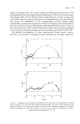
clearly illustrated with two cermet anodes of differing microstructures [20]
operating under identical experimental conditions, at 1000°C in an environment
of hydrogen with 3% HzO. While in both results (Figure 6.7) three components
with similar time constants in each case can be distinguished in the experimental
EIS results, the amplitudes of the corresponding spectral features differ
considerably, and hence the appearance ofthe overall spectra. The anodes differ in
that one consisted of 0.4 pm YSZ powder with bidispersed NiO, 0.4 and 10 pm, to
give after reduction a 40% Ni/60% YSZ porous cermet, the other being prepared
from a submicron fine-grain plasma-processed powder to give 50% Ni/50% PSZ.
By detailed investigation of some experimental model anode systems,
however, a consensus is emerging on the interpretation of anode impedance
I*
,
0.0 0.1 0.2 0.3
z'. Rcm2
1
0.2 - B
N 1 Hr
5 0.1 - 8
C 0
0
N . 10kHz
111
0.0
I
Figure 6.7 Impedance spectral variation with differing cermet microstructures, prepared from a standard
anode formulation (A) and a fine-grain plasma-processed powder (B). Both results distinguish three
dissipative processes with similar time constants in each case. The experimental conditions are identical,
IO00"C in hydrogen, 3% HzO (after 1181). 2' = real or resistive, and 2" the imaginarg or reactive,
coinponentsof thetotdimpedanceZ= 2' + iZ".