
Page 188 - Hybrid-Renewable Energy Systems in Microgrids
P. 188
Sensitivity and transient stability analysis of fixed speed wind generator 169
2
( H t ) d ω t = T m − K s θ − D ω ( t − ω ) (9.6) 2Htdwtdt=Tm−Ksθ−Dwt−wr
r
dt
( H r ) d ω r = T e + K s θ + D ω ( t − ω ) (9.7) 2Hrdwrdt=Te+Ksθ+Dwt−wr
2
r
dt
d θ = ωω ( − ω ) (9.8)
dt b t r dθdt=wbwt−wr
Where w and w are the angular speeds of the turbine and IG, respectively, D, Vsd=RsIsd−wsψsq+1wb.dψsddt
t
r
K , and θ are the mechanical damping coefficient, spring constant, and rotor angle
s
difference between WT and the IG, respectively (all in pu). H and H are the inertia
r
t
constants [sec] of WT and the IG, respectively. T and T are the electromagnetic and
e
m
mechanical torques, respectively.
2.2.1 Induction generator modeling
The equivalent model of the squirrel cage IG using the synchronous rotating reference
frame is shown in Fig. 9.3. The d and q axis stator fluxes and rotor currents are con-
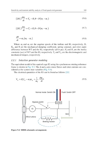
sidered as the system state variables (Fig. 9.4).
The electrical quantities of the IG can be found as follows [21]
1 d ψ
V = R I − ωψ + . sd (9.9)
sd ssd s sq ω b dt
Figure 9.4 SDBR schematic arrangement.