
Page 191 - Hybrid-Renewable Energy Systems in Microgrids
P. 191
172 Hybrid-Renewable Energy Systems in Microgrids
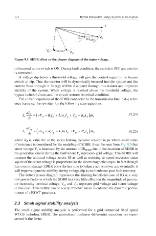
Figure 9.5 SDBR effect on the phasor diagram of the stator voltage.
is bypassed as the switch is ON. During fault condition, the switch is OFF and resistor
is connected.
A voltage dip below a threshold voltage will give the control signal to the bypass
switch to trip. Thus the resistor will be dynamically inserted into the system and the
current flows through it. Energy will be dissipated through this resistor and improves
stability of the system. When voltage is reached above the threshold voltage, the
bypass switch I closes and the circuit restores its initial condition.
The current equations of the SDBR connected to the transmission line in d-q refer-
ence frame can be rewritten by the following state equations:
(
dI
LtdIdtdt=−Vsd−RiIdt+LtwsI L t dt =−V sd − R I + L t ω I + V gd − RI ω ) b (9.24)
sqt
B dt
idt
qt+Vgd−RBIdtwb dt
dI dq
(
LtdIdqdt=−Vsq−RiIqt−LtwsI L t dt =−V sq − R I − L t ω I + V qd − RI ω ) b (9.25)
B qt
iqt
sdt
dt+Vqd−RBIqtwb
where R is value the of the series braking dynamic resistor in pu where small value
B
of resistance is considered for the modeling of SDBR. It can be seen from Fig. 9.5 that
stator voltage V is increased by the amount of IR SDBR due to the insertion of SDBR in
s
the generation circuit during the fault where V represents grid voltage. Thus SDBR will
g
increase the terminal voltage across IG as well as reducing its speed excursion since
square of the stator voltage is proportional to the electromagnetic torque. In fact through
this control strategy SDBR plays the key role to balance active power and eventually it
will improve dynamic stability during voltage dip as well enhance post fault recovery.
The dotted phasor diagram represents the limiting beneficial case of IG at a very
low power factor in which the SDBR has very little effect on the magnitude of genera-
tor increasing terminal voltage. V and V represent grid voltage and stator voltage
g1
s1
in this case. Thus SDBR can be a very effective mean to enhance the dynamic perfor-
mance of a FSWT generator.
2.3 Small signal stability analysis
The small signal stability analysis is performed for a grid connected fixed speed
WTGS including SDBR. The generalized nonlinear differential equations are repre-
sented in the form: