
Page 249 - Improving Machinery Reliability
P. 249
220 Improving Machinery Reliability
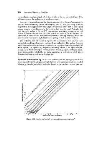
removed using mechanical pull-off devices similar to the one shown in Figure 3-93,
without requiring the application of heat in most cases.
However, it is critical to relate the force requirement F to the proof stresses of the
pull-off bolts connecting fixture and coupling hub. At least four alloy bolts are
required in most applications. The large conventional center bolt in this fixture
should actually be used to remove the coupling hub from the shaft. Note also that
only the solid outline in Figure 3-93 represents an acceptable mechanical pull-off
fixture. Efforts to shortcut this procedure by making a simple fixture similar to the
one shown in dotted outline form incur serious risk of skewing. Skewing, in turn, not
only tends to overstress bolts, but can lead to galling of shaft and bore surfaces.
The hydraulic pull-off fixture of Figure 3-94 accomplishes hub removal under
controlled conditions of pressure, and thus force application. The applied force can
easily be matched or limited to the combined proof strength of the alloy steel pull-off
bolts. Figure 3-95, representing a hydraulic mounting fixture, is the logical compan-
ion device to the hydraulic pull-off fixture of the preceding figure. Hydraulic mount-
ing is rapid, easily controllable, and quite appropriate at installations which do not
have the hub heating facilities outlined earlier.
Hydraulic Hub Dilation. By far the most sophisticated and appropriate method of
mounting and removing large coupling hubs from turbomachinery shafts involve hub
dilation by introducing suitable hydraulic fluids into the interface between shaft sur-
IC 2 1 6 8 I C 2
LBS FORCE REWIRE0 TO OISASSLMBLE SHRINK Fils
Figure 3-93. Mechanical pull-off for tapered-bore coupling