
Page 469 - Industrial Power Engineering and Applications Handbook
P. 469
Testing of metal-enclosed switchgear assemblies 14/443
on the ground. However, for equipment mounted on the
floors of buildings, the floor spectra are determined. To
do this from ground movements the buildingktructure is
analysed and the response time history at various floors
is determined. From these time histories the FRS for
different floors is established. The floor response spectrum
(FRS) so obtained is used as the required response
Response spectrum
spectrum (RRS) for floor-mounted equipment (secondary
systems). The test conditions are developed to simulate
floor spectra. They must also be regarded as the basis of
the design response spectra for all critical equipment
and devices.
The following are the main parameters that must be
considered to arrive at the most appropriate response
spectra:
1 Magnitude of the earthquake, hypocentral distance
0 03 sec 1 C and soil stratification.
--. , Penodic (sec) f = - -- 1 Hz 2 Based on above peak value of ground acceleration,
1
zpA Zone 1 -- f
33 Hz f, frequency (Hz) duration and frequency range.
ZPA = Peak ground or floor acceleration as recorded by the
(Zero period time history. The rest is a response record. An RRS is normally constructed for several levels of
acceleration) critical dampings as illustrated in Figure 14.13. The most
appropriate of these is then chosen for the purpose of
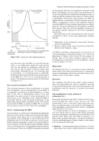
Figure 14.18 A ground or floor response spectrum
testing. Any of the above response spectra can be
developed into a time history of the earthquake. similar
to that in Figure 14. I2(b).
will only trace back the RRS, it is possible that the
object is not sufficiently loaded for such periods Hypocentre
and may fail during an earthquake while the test
may not be able to detect it and the object may This defines the focus, i.e. the point of source within the
wccessfully withstand the test. To overcome such earth’s body, from where the stored energy is released. It
an uncertainty, it is normal practice to artificially causes an earthquake and travels outwards in the form of
broaden the spectral acceleration in the peak regions seismic waves to the earth’s surface.
of the RRS by k 15% T or so (T being periods of
peaks). The broadened spectral peaks are illustrated Epicentre
in Figure 14.17.
This identifies the part of the earth’s surface directly
Zero period acceleration (ZPA) above the hypocentre and where it produces the most
severe ground movements. Away from the epicentre, the
The maximum ground or floor acceleration, as a result acceleration and the intensity of ground movements
of an earthquake, can be obtained from a given RRS. It diminish.
corresponds to acceleration at high frequency, i.e. more
than 33 Hz. This is illustrated in Figure 14.18, and Soil stratification (rocky, alluvial or
represents the peak ground or floor acceleration of a sedimented etc.)
time history of an earthquake, from which the RRS is
developed. During a test, the peak acceleration of the From their focal point to the earth’s surface seismic waves
shake table motion (ZPA) should be at least 10% greater travel through the earth’s crust and the soil. The
than the ZPA of RRS, according to IEEE 344, to account stratification of soil, Le. the earth’s layers above the crust.
for any likely severity in the event of an earthquake. plays an important role, as the intensity and frequencies
of an earthquake, as felt on the earth’s surface, will depend
upon the type of soil strata.
14.6.3 Constructing the RRS It is observed that as a result of damping of soil, the
Seismic analysis is carried out for all important engineering soil may absorb some or most of the energy produced
structures such as dams, bridges and nuclear power plants. during an earthquake, depending upon the thickness and
For regions where these are to be located the likely type of strata. Hence this may help to diminish. to a
expectations of an earthquake as well as the extent of its great extent, ground vibrations, i.e. ground acceleration,
magnitude must be assessed on the basis of the seismic velocity and displacement. Further studies on the subject
history and the earthquake records of the region (Figures have revealed the following:
14.12 to Figure 14.16). Based on these and other factors
such as soil stratification, site dependent response spectra Bedrock Ground displacement in bedrock is less and
are determined. These are the RRS for equipment mounted hence there is no or only a small settlement of a structure