
Page 485 - Industrial Power Engineering and Applications Handbook
P. 485
Instrument and control transformers: application and selection 15/459
Note.$
I A low Loltage of 596, at which the transformer is required to
maintain its accuracy limit, is of great significance. A protection
transformer is required to operate under a fault condition, during
which the primary voltage may dip to a value as low as 5% of
the rated voltage.
2 It is possible to have two windings in the secondary circuit of
a VT when it is required to perform the functions of both
measurement and protection.
VI
I1 Rated voltage factor
This is the multiplying factor which, when applied to the
rated primary voltage, will determine the maximum
voltage at which the transformer will comply with the VI - Primary voltage
thermal requirements for a specified time as well as with V,' - Primary induced emf
the relevant accuracy requirements. This factor carries a
greater significance, particularly on a fault, when healthy Vi - Secondary induced emf referred to the primary side
phases may experience an overvoltage and the protection (V, being secondary induced emf not shown)
VTs may all the more be required to accurately sense In( - Excitation or no-load current
this and activate the protective circuit. Such a situation /, - Loss component of current supplying the hysteresis and eddy
may arise on a ground fault on an isolated neutral system current losses to the voltage transformer core (it is the active
component)
or a high impedance grounded system (Section 20.6). /, - Magnetizing component producing the flux '0' (it is the reactive
Table 15.4, following IEC 60044-2, suggests the component)
recommended voltage factors and their permissible R, - Primary circuit resistance
durations for different grounding conditions. Rg - Secondary circuit resistance referred to the primary side
X, - Primary circuit reactance
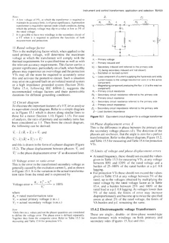
12 Circuit diagram X; - Secondary circuit reactance referred to the primary side
To illustrate the important features of a VT, let us analyse Z, - Primary circuit impedance
its equivalent circuit diagram. Refer to a simple diagram Zg - Secondary circuit impedance referred to the primary side
as in Figure 15.1 which is drawn along similar lines to Z- Load (burden) impedance
those for a motor (Section 1.10, Figure 1.15). For ease Figure 15.1 Equivalent circuit diagram for a voltage transformer
of analysis, the ratio of primary and secondary turns has
been considered as 1 : I. Then from the circuit diagram, 14 Phase displacement errol; 6
the following can be derived: This is the difference in phase between the primary and
the secondary voltage phasors (6). The direction of the
phasors are so chosen, that the angle is zero for a perfect
transformation. Refer to the phasor diagram, Figure 15.2,
and Table 15.5 for measuring and Table 15.6 for protection
and this is drawn in the form of a phasor diagram (Figure VTs .
15.2). The phase displacement between phasors and
Vi is the phase displacement error '6' as discussed later. 15 Limits of voltage and phase displacement errors
At rated frequency, these should not exceed the values
13 Voltage error or ratio error given in Table 15.5 for measuring VTs. at any voltage
This is the error in the transformed secondary voltage as between 80% and 120% of the rated voltage and a
burden of 25-100% of the rated burden at a p.f. 0.8
generally caused by the excitation current I,, and as shown
in Figure 15. 1. It is the variation in the actual transforma- lagging.
tion ratio from the rated and is expressed by For protection VTs these should not exceed the values
given in Table 15.6 at any voltage between 5% of the
rated, up to the voltages obtained by multiplying the
K, V,* - V,* rated voltage by the rated voltage factor as in Table
Voltage error = x 100%
15.4, and a burden between 25% and 100% of the
rated load at a p.f. 0.8 lagging. At voltages lower than
where 5% of the rated, the limits of error may increase
K, = rated transformation ratio disproportionately and become up to twice the specified
VI = actual primary voltage (r.m.s.) errors at about 2% of the rated voltage. the limits of
V, = actual secondary voltage (r.m.s.) VA burden and p.f. remaining the same.
NO I e 15.4.2 Electromagnetic voltage Transformers
*Only the r.rn.s. values and not the phasor quantities are considered
to define the voltage error. The phase error is defined separately. These are single-, double- or three-phase wound-type
Together they form the composite error. Refer to Table 15.5 for trans-formers with windings on both primary and
rneawring and Table 15.6 for protection VTs. secondary sides (Figures 15.3(a) and (b)).