
Page 488 - Industrial Power Engineering and Applications Handbook
P. 488
15/462 Industrial Power Engineering and Applications Handbook
R Y B Healthy system
1 1 1 In this case, all the three phases would be balanced and
the residual voltage, Ve, will be zero. The three voltage
phasors in the open delta windings will be as illustrated
in Figure 15.5(a). The phasor sum of these phasors is
zero. Therefore V, = 0.
=G
Ground fault on one phase
System neutral grounded
voltage Consider a ground fault on phase R. The voltage across
this phase will become zero and the phasor diagram will
be as illustrated in Figure 15.5(b). The other two phasors
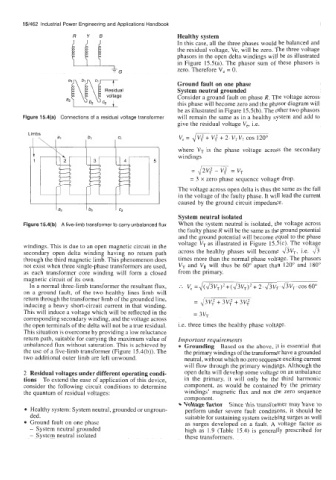
Figure 15.4(a) Connections of a residual voltage transformer will remain the same as in a healthy system and add to
give the residual voltage V,, i.e.
v, = JVT' + v; + 2.V,VT cos 120"
where VT is the phase voltage across the secondary
windings
5
=2/2v:-vT2=vT
= 3 x zero phase sequence voltage drop.
The voltage across open delta is thus the same as the fall
in the voltage of the faulty phase. It will lead the current
caused by the ground circuit impedance.
System neutral isolated
Figure 15.4(b) A five-limb transformer to carry unbalanced flux When the system neutral is isolated, the voltage across
the faulty phase R will be the same as the ground potential
and the ground potential will become equal to the phase
voltage VT as illustrated in Figure 15.5(c). The voltage
windings. This is due to an open magnetic circuit in the
secondary open delta winding having no return path across the healthy phases will become 8VT, i.e. &
through the third magnetic limb. This phenomenon does times more than the normal phase voltage. The phasors
not exist when three single-phase transformers are used, V, and V, will thus be 60" apart than 120" and 180"
as each transformer core winding will form a closed from the primary.
magnetic circuit of its own.
In a normal three-limb transformer the resultant flux, .'. v, =J(&~T)'+(&~T)*+ 2~&v~.&v~~COS60"
on a ground fault, of the two healthy lines limb will
return through the transformer limb of the grounded line, = J3v; + 3v; + 3v;
inducing a heavy short-circuit current in that winding.
This will induce a voltage which will be reflected in the = 3vT
corresponding secondary winding, and the voltage across
the open terminals of the delta will not be a true residual. i.e. three times the healthy phase voltage.
This situation is overcome by providing a low reluctance
return path, suitable for carrying the maximum value of Important requirements
unbalanced flux without saturation. This is achieved by Grounding Based on the above, it is essential that
the use of a five-limb transformer (Figure 15.4(b)). The the primary windings of the transformer have a grounded
two additional outer limb are left unwound. neutral, without which no zero sequence exciting current
will flow through the primary windings. Although the
2 Residual voltages under different operating condi- open delta will develop some voltage on an unbalance
tions To extend the ease of application of this device, in the primary, it will only be the third harmonic
consider the following circuit conditions to determine component, as would be contained by the primary
the quantum of residual voltages: windings' magnetic flux and not the zero sequence
component.
Voltage factor Since this transformer may have to
Healthy system: System neutral, grounded or ungroun- perform under severe fault conditions, it should be
ded. suitable for sustaining system switching surges as well
Ground fault on one phasc as surges developed on a fault. A voltage factor as
- System neutral grounded high as 1.9 (Table 15.4) is generally prescribed for
- System neutral isolated these transformers.