
Page 486 - Industrial Power Engineering and Applications Handbook
P. 486
15/460 Industrial Power Engineering and Applications Handbook
Vl
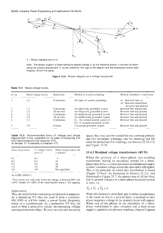
6 = Phasor displacement error
Note The phasor diagram is drawn taking the applied voltage VI as the reference phasor. It can also be drawn
taking the primary induced emf V,' as the reference. The logic to the diagram and the subsequent results shall
however, remain the same.
Figure 15.2 Phasor diagram for a voltage transformer
Table 15.4 Rated voltage factors
Sr: no. Rated voltage factor Rated time Method .f system grounding Method of primary connections
~~ ~ ~ ~- -. ~~
1 1.2 Continuous All types of system grounding (i) Between lines or
(ii) Between transformer
star point and ground
2 1.2 Continuous An effectively grounded system Between line and ground
3 1.5 30 seconds An effectively grounded system Between line and ground
4 1.2 Continuous An ineffectively grounded system Between line and ground
5 1.9 30 seconds An ineffectively grounded system Between line and ground
6 1.2 Continuous (i) An isolated neutral system or Between line and ground
(ii) A resonant grounded system
7 1.9 8 hours A resonant grounded system Between line and ground
~
Table 15.5 Recommended limits of voltage and phase space, they may also be wound for one common primary
displacement errors, applicable for all types of measuring VTs and two secondary windings, one for metering and the
(only electromagnetic and capacitor VTs). other for protection. For markings, see Section 15.10.1(2)
(A residual VT is basically a protection VT)
and Figure 15.35.
Class of accuracy 6 voltage (ratio) Phase displacement (6)
error fa _+ minutey 15.4.3 Residual voltage transformers (RVTs)
-~ ~
0.1 0.1 5 When the primary of a three-phase two-winding
0.2 0.2 10 transformer, having its secondary wound for a three-
0.5 0.5 20 phase open delta, is connected across an unbalanced supply
1 .Q 1 .o 40 system, a residual voltage across the open delta will appear.
3.0 3.0 Not specified This is the principle on which this transformer is based
(Figure 15.4(a)). As discussed in Section 21.2.2, and
As in IEC-60044-2
illustrated in Figure 21.7, the phasor sum of all the three
"These errors are valid only when the voltage is between 80% and line to ground voltages in a three-phase balanced system
120%, burden 25-1006 of the rated burden and p.f., 0.8 lagging. is zero, i.e.
v, + v, + v, = 0
Application
They are used for both measuring and protection purposes. When this balance is disturbed, due to either an unbalance
As a measuring VT, they are used to feed a voltmeter, in the loads or due to a ground fault, a residual or zero
kW, kWh or a kVAr meter, a power factor, frequency phase sequence voltage in the neutral circuit will appear.
meter or a synchroscope. As a protection VT they are When one of the phases in the secondary of a three-
used to feed a protective circuit, incorporating voltage phase transformer is open circuited and a three-phase
sensing protection relays. To save on cost and mounting supply is applied to its primary windings, there will appear