
Page 487 - Industrial Power Engineering and Applications Handbook
P. 487
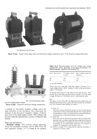
Instrument and control transformers: application and selection  15/461


                   Transformers with HT fuse

          Figure 15.3(a)  Typical indoor epoxy resin cast instrument voltage transformers up to  11 kV (Courtesy: Kappa Electricals)


                                                     Table  15.6  Recommended  limits  of  voltage  and  phase
                                                     displacement  errors,  applicable  for  all  types  of  protection  VTs
                                                     (electromagnetic, capacitor and residual VTs)
                                                     Class of accuracy   % voltage (ratio)  Phase displacement (6)
                                                                    error?       fminutes

                                                     3P             3.0          120
                                                     6P             6.0          240
                                                     As per IEC-60044-2
                                                     aThese errors are valid  only  when  the-voltage  is between  5% to
                                                     ‘rated voltage factor x loo%’, burden 25-100%  of the rated burden,
                                                     and p.f., 0.8 lagging.
                          t
                          a                          At voltages lower than 5%, the limits of error may increase. They
                                                 9   become up to twice the specified errors at about 2% of the rated
                                                     voltage, the limits of VA burden  and p.f. remaining the same.
                                                     Note
                            (b) 11 kV three-phase indoor   The choice of class 3P or 6P will depend upon the application and
      (a) 33 kV single-phase outdoor                 the protection scheme of the system.  The following may be considered
       Figure 15.3(b)  Typical HT instrument voltage transformers   as a rule of thumb when making this choice.
      a  residual  or  zero  phase  sequence  voltage  across  the   (i)  Class 3P
      open  terminals  at  the  secondary.  This  represents  the   This class may be selected for protective devices that operate
      residual  or the zero phase  sequence voltage,  whatever   on the basis of phase relationship between the voltage and the
                                                         current phasors, such as in a directional overcurrent protection,
      may exist in the main supply system. This voltage will   reverse power or directional distance protection.
      be zero when the main primary system is balanced and   (ii) Class 6P
      healthy.                                           This class may be selected for protective devices where their
                                                         operation does not depend upon the phase relationship between
      Important parameters                               the voltage and the current phasors, such as for an overvoltage,
      1 Residual voltage  The  residual  voltage  appearing   overcurrent or  an  undervoltage protection.  For  instance, a
                                                         residual VT should have this accuracy class.
      across  the  secondary  windings  will be three times  the   (iii) When a residual VT is employed for capacitor discharges it
      zero  sequence  voltage,  if  it  is  found  in  the  primary   requires no accuracy class.