
Page 492 - Industrial Power Engineering and Applications Handbook
P. 492
15/466 Industrial Power Engineering and Applications Handbook
Z
V1/d3
R
During resonance, when:
X, = X, the circuit would behave like a normal transformer
V, : Voltage drop across the line capacitors
V, : Voltage drop across the inductance
Rl : Primary resistance representing losses across '@ and 'L' and
the intermediate voltage transformer (EMU)
R;: Secondary resistance of the intermediate VT referred to the ts bn
primary side.
Figure 15.9 A typical outdoor type oil-filled 11 kV control
/A : Loss component transformer
Irn : Magnetizing component
Z: Load (burden) impedance switchgear or a controlgear assembly not supposed to be
R : Damping resistor to prevent ferro-resonance effects
connected directly to the main supply. These transformers
do not require a high accuracy and can be specified by
Figure 15.7 Equivalent circuit diagram of a CVT
the following parameters:
Rated primary voltage The normal practice for an
2 To feed the synchronizing equipment. HT system is to provide a separate LT feeder for the
3 As a coupling unit for carrier signals (Section 23.5.2 auxiliary supplies. The primary voltage will be the
and Figure 23.9(b)). normal system voltage, V,., when the transformer is
4 To damp the transient voltages on the primary side. connected line to line or Vr1a when connected line
to neutral.
For markings refer to Section 15.10.1 and Figure 15.35. Rated secondary voltage This is 24,48, 11 0, 220,
230, 240 or 250 volts, or according to the practice of
15.4.5 Control transformers a country. Tappings, if required, can be provided on
the primary side.
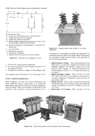
Refer to Figures 15.8 and 15.9. These transformers are Rated burden This is the maximum burden the
quite different from a measuring or a protection transformer may have to feed at a time. The preferred
transformer, particularly in terms of accuracy and short- ratings will follow series R-10 of ISO-3 (Section
time VA ratings. They are installed to feed power to the 13.4.1(4)).
control or the auxiliary deviceslcomponents of a Short-time VA burden This accounts for the
Figure 15.8 Typical single-phase and three-phase control transformers