
Page 494 - Industrial Power Engineering and Applications Handbook
P. 494
15/468 Industrial Power Engineering and Applications Handbook
will be maintained within the prescribed limits. Figure transformer 41 511 10 V.
15.10 illustrates this requirement and Example 15.1 The following data have been assumed:
demonstrates the procedure to determine the required VA System: 415 V, three-phase, four wire.
of a control transformer.
Control voltage: 11 0 V a.c.
Example 15.1 Control wire: 2.5 mm2 (resistance of wire = 7.6 Q/lOOO m, as
Consider the control scheme of an auto-control capacitor in Table 13.15).
panel as shown in Figure 23.37. The scheme shows the
control voltage as being tapped from the main bus. But for Approximate length of wire for each feeder up to the power
our purpose, we have considered it through a control factor correction relay (PFCR): 35 m.
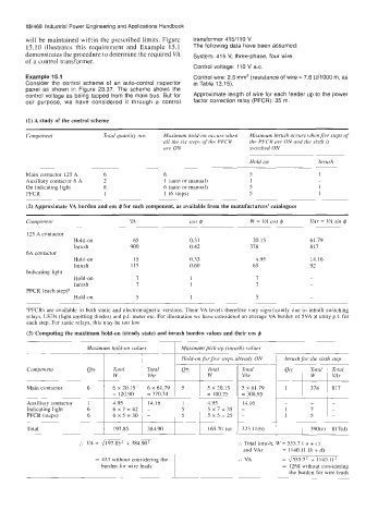
(1) A study of the control scheme
Component Total quantity nos Maximum hold-on occurs when Maximum inrush occurs whenfive steps of
all the six steps of the PFCR the PFCR are ON and the sixth is
are ON switched ON
Hold on Inrush
Main contactor 125 A 6 6 5 1
Auxiliary contactor 6 A 2 1 (auto or manual) 1 -
On indicating light 8 6 (auto or manual) 5 1
PFCR 1 1 (6 steps) 5 1
- ~ -
(2) Approximate VA burden and cos f$ for each component, as available from the manufacturers’ catalogues
Componenr VA cos @ W = VA cos @ VAr = VA sin @
125 A contactor
Hold-on 65 0.3 I 20.15 61.79
Inrush 900 0.42 378 817
6A contactor
Hold-on 15 0.33 4.95 14.16
Inrush 115 0.60 69 92
Indicating light
Hold-on 7 I 7 -
Inrush 7 1 7 ~
PFCR (each step)a
H o 1 d - o n 5 1 5 -
aPFCRs are available in both static and electromagnetic versions. Their VA levels therefore vary significantly due to inbuilt switching
relays, LEDs (light emitting diodes) and p.f. meter etc. For illustration we have Considered an average VA burden of 5VA at unity p.f. for
each step. For static relays, this may be too low
(3) Computing the maximum hold-on (steady state) and inrush burden values and their cos f$
1
Maximum hold-on values Maximum pick-up (inrush) values
Hold-on for five steps already ON 1 Inrush for the sixth step
Component Qty Total Total Qty Total Total Qty , Total , Total
W VA r W VA r I W VAr
Main contactor 6 6 x 20.15 6 x61.79 5 5 x 20.15 5 x 61.79 1 378 817
= 120.90 = 370.74 = 100.75 = 308.95
Auxiliary contactor 1 4.95 14.16 I 4.95 14.16 - - -
Indicating light 6 6~7=42 - 5 5x7=35 - 1 7 -
PFCR (steps) 6 6X5=30 - 5 5X5=25 - 1 5 -
Total 197.85 384.90 165.70 (a) , 323.11(b) ~ 1 390(cj 1 817(d)
:. VA = J197.852 + 384.90’ :. Total inrush, W = 555.7 ( a + c)
and VAr = 1140.11 (b + d)
= 433 without considering the :. VA = 4555.7’ + 1140.11’
burden for wire leads = 1268 without considering
the burden for wire leads