
Page 495 - Industrial Power Engineering and Applications Handbook
P. 495
Instrument and control transformers: application and selection 15/469
Corrrrol c.irc.ciit currmf Control circuit current
IL = 43311 IO = 3.94A
and lead burden = IL’ . K I, = 1268/110 = 11.53A
where R is the resistance of the connecting wires at the and lead burden = 1 I .53’ x 2.035
operating temperature (90°C, as in Table 14.5)
76 = 270.53 W
+
= 6 X 35 X - 3.93 x IO-’ (90-20)1 (2 ~
[I
I000 :. Total maximum inrush burden
(for details refer to Table 14.4) I
~ W = 555.7 + 270.53
= 2.035 R I
:.Lead burden = 3.94’ x 2.035 i = 826.23
= 31.59 W and VAr = l14n.1 I
:. Total maximum steady-state hold-on burden l 1
I+’= 197.85 + 31.59 = 229.44 :. Maximum short-time VA = d826.23’ + 1140.1 I’
And VAr = 384.9 = 1408.0
:.Maximum VA = 4229.44’ + 384.9’ ~ I at an inrush (short-time) cos 6 = 826.23
= 448. 1 1408.0
229.44
at a steadq-\tate cos d = - = 0.587
448. I0
= 0.51
Rating of control transformer
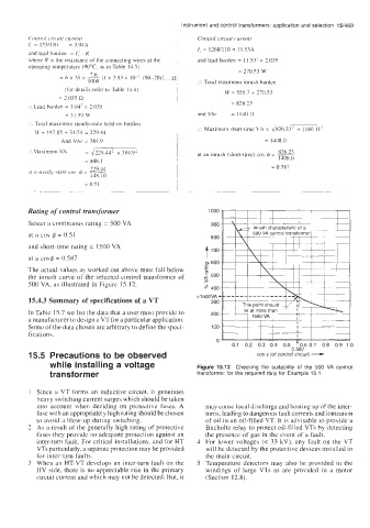
Select a continuous rating = 500 VA
at a COS 4 = 0.51
and short-time rating = 1500 VA
at a coyb = 0.5X7
The actual values a5 worked out above must fall below
the inrush curve of the selected control transformer of
500 VA, as illustrated in Figure 15.12.
15.4.3 Summary of specifications of a VT
In Table 15.7 we list the data that a user must provide to
a manufacturer to design a VT for a particular application.
Some of the data chosen are arbitrary to define the speci-
fications. cos @(of control circuit) -
15.5 Precautions to be observed 0 587 0
while installing a voltage Figure 15.12 Checking the suitability of the 500 VA control
transformer transformer for the required duty for Example 15 1
I Since a VT forms an inductive circuit, it generates
heavy switching current surges which should be taken
into account when deciding on protective fubeb. A may cause local discharge and heating up of the inter-
fuse with an appropriately high rating should be chosen turns, leading to dangerous fault currents and ionization
to avoid a blow-up during switching. of oil in an oil-filled VT. It is advisable to provide a
2 As a result of the generally high rating of protective Bucholtz relay to protect oil-filled VTs by detecting
fuses they provide no adequate protection against an the presence of gas in the cvcnt of a fault.
inter-turn fault. For critical installations, and for HT 4 For lower voltages (c 33 kV), any fault on the VT
VTs particularly, a separate protection may be provided will be detected by the protective devices installed in
for inter-turn faults. the main circuit.
3 When an HT-VT develops an inter-turn fault on the 5 Temperature detectors may also be provided in the
HV side, there is no appreciable rise in the primary windings of large VTs as are provided in a motor
circuit current and which may not be detected. But, it (Section 12.8).