
Page 496 - Industrial Power Engineering and Applications Handbook
P. 496
15/470 Industrial Power Engineering and Applications Handbook
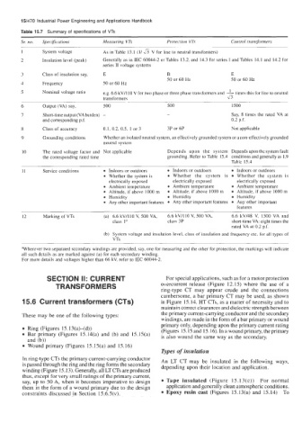
Table 15.7 Summary of specifications of VTs
Sr: no. Specifcations Measuring VTs Protection VTs Control transformers
- - ~~~
1 System voltage As in Table 13.1 (I/& V for line to neutral transformers)
2 Insulation level (peak) Generally as in IEC 60044-2 or Tables 13.2, and 14.3 for series I and Tables 14.1 and 14.2 for
series I1 voltage systems
3 Class of insulation say, E B E
50 or 60 Hz 50 or 60 Hz
4 Frequency 50 or 60 Hz
5 Nominal voltage ratio e.g. 6.6 kV/l IO V for two phase or three phase transformers and 1 this for line to neutral
times
transformers 36
- ~
6 Output (VA) say, 500 500 1500
I Short-time output (VAburden) - - Say, 8 times the rated VA at
and corresponding p.f. 0.2 p.f.
8 Class of accuracy 0.1, 0.2, 0.5, 1 or 3 3P or 6P Not applicable
9 Grounding conditions Whether an isolated neutral system, an effectively grounded system or a non-effectively grounded
neutral system
10 The rated voltage factor and Not applicable Depends upon the system Depends upon the system fault
the corresponding rated time grounding. Refer to Table 15.4 conditions and generally as 1.9
Table 15.4
~
11 Service conditions Indoors or outdoors Indoors or outdoors Indoors or outdoors
Whether the system is 0 Whether the system is Whether the system is
electrically exposed electrically exposed electrically exposed
Ambient temperature Ambient temperature Ambient temperature
Altitude, if above 1000 m 0 Altitude, if above 1000 m Altitude, if above 1000 m
Humidity 0 Humidity Humidity
Any other important features Any other important features Any other important
features
-
12 Marking of VTs (a) 6.6 kV/lIO V, 500 VA, 6.6 kV/110 V, 500 VA, 6.6 kV/48 V, 1500 VA and
class I" class 3P short-time VA: eight times the
rated VA at 0.2 p.f.
System voltage and insulation level, class of insulation and frequency etc. for all types of
VTs
-
~
aWherever two separated secondary windings are provided, say, one for measuring and the other for protection, the markings will indicate
all such details as are marked against (a) for each secondary winding.
For more details and voltages higher than 66 kV, refer to IEC 60044-2.
SECTION II: CURRENT For special applications, such as for a motor protection
TRANSFORMERS overcurrent release (Figure 12.15) where the use of a
ring-type CT may appear crude and the connections
cumbersome, a bar primary CT may be used, as shown
15.6 Current transformers (CTs) in Figure 15.14. HT CTs, as a matter of necessity and to
maintain correct clearances and dielectric strength between
These may be one of the following types: the primary current-carrying conductor and the secondary
windings, are made in the form of a bar primary or wound
primary only, depending upon the primary current rating
Ring (Figures 15.13(a)-(d)) (Figures 15.15 and 15.16). Inawoundprimary, theprimary
Bar primary (Figures 15.14(a) and (b) and 15.15(a) is also wound the same way as the secondary.
and (b))
Wound primary (Figures 15.15(a) and 15.16)
Types of insulation
In ring-type CTs the primary current-carrying conductor An LT CT may be insulated in the following ways,
is passed through the ring and the ring forms the secondary depending upon their location and application.
winding (Figure 15. 13). Generally, all LT CTs are produced
thus, except for very small ratings of the primary current,
say, up to 50 A, when it becomes imperative to design Tape insulated (Figure 15.13(c)) For normal
them in the form of a wound primary due to the design application and generally clean atmospheric conditions.
constraints discussed in Section 15.6.5(v). Epoxy resin cast (Figures 15.13(a) and 15.14) To