
Page 501 - Industrial Power Engineering and Applications Handbook
P. 501
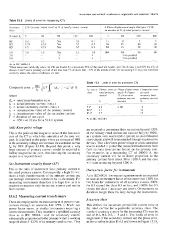
Accuracy   2 % Current (ratio) erroP at % of  rated primary  current   + Phase displacement angle 6 (Figure 15.18)
       class                                                     in minutes at % of rated primary current
                     ~
       % rated. I,   5    20        50        100      120        5        20       100       120
       0.1      0.4       0.2       NA         0.1       0.1      15        8         5         5
       0.2      0.75      0.35      NA         0.2       0.2      30       15        10        10
       0.5       1.5      0.75      NA         0.5       0.5      90       45        30        30
       1 .o     3.0       1.5       NA         1 .o      1 .o    180       90        60        60
       3.0      -         -          3         -         3                  Not specified
       5.0      -         -          5         -         5                  Not specified


                                                      Table 15.9  Limits of error for protection CTs
                      loo
       Composite error  = - il/T joT (K; i2 - i,)*  dt %
                       I1                             Accuracy  Current error at  Phase displacement  Composite error
                                                      class   rated primary   angle 6 (Figure   at rated
       where                                                 current     15.18 at rated   accuracy limit
       K,, = rated transformation  ratio                     %          primary current   primary current
                                                                         minutes
                                                                                       %
       I,  = actual primary current (r.m.s.)           ~
       I2  = actual secondary current (r.m.s.)        5P     +1          + 60          5
       i,  = instantaneous value of the primary current   10P   *3       -             10
       i2  = instantaneous value of the secondary current   15P   +5     -             15
       T  = duration of one cycle
         =  1/50 s or 20 ms for a 50 Hz system.       As  in IEC 60044-1
       (viii) Knee point voltage
                                                      are required to commence their saturation beyond  120%
       This is the point on the magnetic curve of the laminated   of the primary rated current and saturate fully by 500%,
       core of  the CT at which the saturation  of the core will   as a system is not warranted to operate on an overload or
       start. It is defined as the point where an increase of 10%   short-circuit, and will be interrupted through its protective
       in the secondary voltage will increase the excitation current   devices. Thus a low knee-point voltage or a low saturation
       I,,,  by  50% (Figure  15.19). Beyond  this  point,  a  very   level is needed to protect the connected instruments from
       large amount of primary  current  would  be required  to   fault currents (overcurrent factor) on the primary  side.
       further magnetize the core, thus limiting the secondary   For  example,  in  a  measuring  CT of  1000/5  A,  the
       output to a required  level.                   secondary  current  will  be  in  direct  proportion  to  the
                                                      primary  current from about 50 to  1200 A and the core
      (ix) Instrument security factor (SF)            will start saturating beyond  1200 A.

      This is the ratio of instrument limit primary  current to   Overcurrent factor for instruments
      the rated primary  current. Consequently a high SF will
       mean a high transformation of  the primary  current and   As in IEC 6005 1, the measuring instruments are required
      can damage instruments connected to its secondary. For   to have an overcurrent factor of not more than 120% for
      measuring  instruments therefore it is kept low, as it is   two hours for instruments of all accuracy classes, 200%
      required to measure only the normal current and not the   for 0.5 second for class 0.5 or less, and  1000% for 0.5
       fault current.                                 second for class  1 accuracy and above. Overcurrents or
                                                      durations longer than this may damage the instruments.
       15.6.2  Measuring current transformers
                                                      Accuracy class
       These are employed for the measurement of power circuit
       currents  through  an  ammeter,  kW,  kWh  or KVAr  and   This defines the maximum permissible current error at
       power  factor meter,  or similar instruments requiring  a   the  rated  current  for  a  particular  accuracy  class.  The
       current measurement. They must have a specified accuracy   standard accuracy classes for the measuring CTs may be
       class  as  in  IEC  60044-1  and  the  secondary  current   one of 0.1,  0.2, 0.5,  1,  3 and 5. The limits of error in
       substantially proportional to the primary within a working   magnitude of the secondary current and the phase error,
      range of about 5-120%  of its primary rated current. They   as discussed in Section 15.6.1 and shown in Figure 15.18,