
Page 505 - Industrial Power Engineering and Applications Handbook
P. 505
Instrument and control transformers: application and selection 15/479
15.6.6 Special-purpose current transformers,
type 'PS'
These are protection CTs for special applications such as
biased differential protection, restricted ground fault
protection and distance protection schemes, where it is
not possible to easily identify the class of accuracy, the
accuracy limit factor and the rated burden of the CTs and
where a full primary fault current is required to be
transformed to the secondary without saturation, to
accurately monitor the level of fault and/or unbalance.
The type of application and the relay being used determine
the knee point voltage. The knee point voltage and
the excitation current of the CTs now form the basic
design parameters for such CTs. They are classified as
class 'PS' CTs and can be identified by the following
characteristics:
CTR = lplI\
Rated test winding current
0 Nominal turn ratio (the error must not exceed k 0.25%)
Knee point voltage (kpv) at the maximum secondary
turns,
u
L 2 -G
v, 2 2v*,
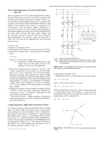
f,, F2 - 2 sets of identical class PS CTs
where Vk = knee point voltage and Relay - High impedance three element differential protection relay
V, = maximum voltage developed across the Wp - Windings of a power equipment or section of a power system
relay circuit by the other group of CTs to be protected
during a severe most through fault.
Figure 15.22 A circulating current scheme to provide a phase
Maximum magnetizing (excitation) current at the and a ground fault differential protection
voltage setting (VfJ of the relay or at half the knee
point e.m.f. to be 5 30 mA for 1 A CTs for most high- as illustrated in Figure 15.23.
impedance schemes. The manufacturers select a proper
iron core to limit this to help reduce the effective relay Applying this law to a three-phase, three wire system.
+
current setting and improve its sensitivity. Magnetizing iR i, + iB = 0
characteristics, V, versus I,,,, (V, being the CT secondary
voltage under rated conditions), as shown in Figure and to a three-phase four-wire system
IS. 19, are provided by the manufacturer to facilitate
relay setting. I, + iu + I, + I, = o
Maximum resistance of the secondary winding corrected
to 90°C or the maximum operating temperature When a three-phase four-wire system feeds non-linear
considered. In fact, it should be substituted by the or single-phase loads this balance is upset and the
actual operating temperature. unbalanced current flows through the neutral. The same
We discuss below a high-impedance differential relationship can be expressed as
-
-
-
protection scheme to provide a detailed procedure to - IR + IY + 10 = In.
sclect PS Class CTs.
1 High-impedance differential protection scheme
The scheme primarily detects an inter-turn fault, a ground
fault or a phase fault. It can thus protect a bus system
and windings of critical machines such as generators,
transformers and reactors in addition to a ground fault.
The differential system is a circulating current system
between the two winding terminals of the equipment or
each section of a multi-section bus system being protected
as illustrated in Figure 15.22. The scheme is based on
Kirchhoff's law, which defines that the phasor sum of ....
the currents entering a node is zero, i.e. I, + I, + I, + I, = 0
_ - _ - Figure 15.23 Kirchhoffs law - sum of currents entering a node
II + I. + 13 + I? = 0 is zero