
Page 510 - Industrial Power Engineering and Applications Handbook
P. 510
15/484 Industrial Power Engineering and Applications Handbook
these quantities may be considered in phase with each
other, with little error,
:. Isf = I, -k Ist
If there are N number of CTs connected in parallel, the
magnetizing current will flow through all of them. In a
GF protection scheme all the three CTs of all the feeders
being protected together will fall in parallel, while in
case of a combined GF and phase fault protection scheme, Non-linear
only one third of these CTs will fall in parallel. The CT resistor
in the faulty circuit must be able to draw enough current Stabilizing
to feed the magnetizing losses of all the CTs falling in resistor
parallel and the relay pickup current, ISt. The sensitivity Relay
of the differential scheme can therefore be expressed
more appropriately as
(N being the number of CTs falling in parallel) and in
terms of the primary
Since it determines the sensitivity level of the protection
scheme, it must be kept as low as possible to detect even L
-G
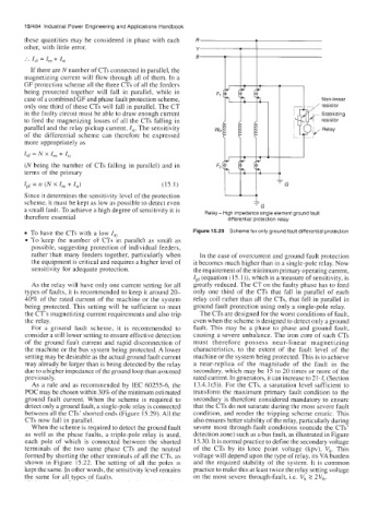
a small fault. To achieve a high degree of sensitivity it is Relay- High impedance single element ground fault
therefore essential differential protection relay
To have the CTs with a low I, Figure 15.29 Scheme for only ground fault differential protection
To keep the number of CTs in parallel as small as
possible, suggesting protection of individual feeders,
rather than many feeders together, particularly when In the case of overcurrent and ground fault protection
the equipment is critical and requires a higher level of it becomes much higher than in a single-pole relay. Now
sensitivity for adequate protection. the requirement of the minimum primary operating current,
Ipf (equation (lS.l)), which is a measure of sensitivity, is
As the relay will have only one current setting for all greatly reduced. The CT on the faulty phase has to feed
types of faults, it is recommended to keep it around 20- only one third of the CTs that fall in parallel of each
40% of the rated current of the machine or the system relay coil rather than all the CTs, that fell in parallel in
being protected. This setting will be sufficient to meet ground fault protection using only a single-pole relay.
the CT’s magnetizing current requirements and also trip The CTs are designed for the worst conditions of fault,
the relay. even when the scheme is designed to detect only a ground
For a ground fault scheme, it is recommended to fault. This may be a phase to phase and ground fault,
consider a still lower setting to ensure effective detection causing a severe unbalance. The iron core of such CTs
of the ground fault current and rapid disconnection of must therefore possess near-linear magnetizing
the machine or the bus system being protected. A lower characteristics, to the extent of the fault level of the
setting may be desirable as the actual ground fault current machine or the system being protected. This is to achieve
may already be larger than is being detected by the relay a near-replica of the magnitude of the fault in the
due to a higher impedance of the ground loop than assumed secondary, which may be 15 to 20 times or more of the
previously. rated current. In generators, it can increase to 21. I, (Section
As a rule and as recommended by IEC 60255-6, the 13.4.1(5)). For the CTs, a saturation level sufficient to
POC may be chosen within 30% of the minimum estimated transform the maximum primary fault condition to the
ground fault current. When the scheme is required to secondary is therefore considered mandatory to ensure
detect only a ground fault, a single-pole relay is connected that the CTs do not saturate during the most severe fault
between all the CTs’ shorted ends (Figure 15.29). All the condition, and render the tripping scheme erratic. This
CTs now fall in parallel. also ensures better stability of the relay, particularly during
When the scheme is required to detect the ground fault severe most through-fault conditions (outside the CTs’
as well as the phase faults, a triple-pole relay is used, detection zone) such as a bus fault, as illustrated in Figure
each pole of which is connected between the shorted 15.30. It is normal practice to define the secondary voltage
terminals of the two same phase CTs and the neutral of the CTs by its knee point voltage (kpv), V,. This
formed by shorting the other terminals of all the CTs, as voltage will depend upon the type of relay, its VA burden
shown in Figure 15.22. The setting of all the poles is and the required stability of the system. It is common
kept the same. In other words, the sensitivity level remains practice to make this at least twice the relay setting voltage
the same for all types of faults. on the most severe through-fault, Le. V, 2 2V,.