
Page 508 - Industrial Power Engineering and Applications Handbook
P. 508
15/482 Industrial Power Engineering and Applications Handbook
n T Sensitivity
T I This is the ability of the scheme to detect the weakest
tit
Y internal fault.
Stability
This can be defined by the most severe external fault at
which the scheme will remain inoperative. It should also
remain inoperative in healthy conditions. That is it should
be immune to the momentary voltage or current transients
Relay and normal harmonic contents in the circulating current.
Series LC-filter circuits are generally provided with the
relay coil to suppress the harmonics and to detect the
fault current more precisely.
Use of stabilizing resistance
It is possible that the voltage Vf, may become sufficiently
high to cause a spill current on a through-fault higher
than the relay pick-up current, I,[. To ensure that no spill
current higher than the relay setting, Is,, will flow through
the relay circuit under a through-fault condition, the
impedance of the relay circuit is raised substantially. It
can be obtained by using a stabilizing resistance, R,,,
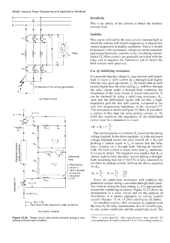
(a) Power circuit such that the differential circuit will act like a high-
impedance path for this spill current, compared to the
very low magnetizing impedance of the saturated CT.
L, This resistance is shown in Figure 15.26(b). It will allow
a current of less than the relay pickup current, Is,. To
fulfil this condition, the impedance of the differential
circuit must be a minimum to ensure
The normal practice is to choose R,, based on the setting
voltage required. In the above equation, Vft is the minimum
voltage required across the relay branch (R, + Rst) for
pushing a current equal to I,, to ensure that the relay
stays immune on a through-fault. During an internal-
fault, the fault current is much more than I,,, and hence
it is easy to detect. The equation also implies that R,, is
chosen high to limit the relay current during a through-
fault (assuming that one of the CTs is fully saturated) to
less than its pickup current. Solving the above equation
for R,,,
short circuited
Since the additional resistance will stabilize the
protective scheme during a maximum through-fault condi-
tion without raising the relay setting, Is,, it is appropriately
termed the stabilizing resistance. Figure 15.27 shows an
arrangement in a relay circuit and for the purpose of
illustration, it is shown separately in various control
L2
circuits (Figures 15.24, 15.25(b) and Figure 25.26(b)).
Vn = & (RCT + RO As standard practice, this resistance is supplied with
I,, = Fault level of the equipment under protection the relay by the relay manufacturer. It is of variable type,
to suit system conditions and the actual fault level. The
(b) Control scheme
Figure 15.26 Power circuit and control scheme during a very *This is relay-specific. The manufacturer may specify VA
severe external fault condition corresponding to its rated current of 1 A or 5 A or setting current I??