
Page 507 - Industrial Power Engineering and Applications Handbook
P. 507
Instrument and control transformers: application and selection 15/481
i-
I
I '$ G (Neutral of the winding grounded)
I_--*---,
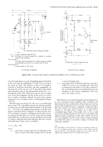
F,, F2 - 2 sets of identical class PS CTs.
Wp - Windings of a power equipment or section of a power
system to be protected
Fault location 1: L2
The relay stays inoperative for a fault occurring outside
the protected zone even if it is within the CTs zone Small spill current through the relay
fault location 2: I,, = IC2 ~ ci
It falls outside the CTs zone.
(a) Principle of operation (bj Control circuit diagram
Figure 15.25 A through-fault condition outside the protected zone in a differential scheme
share the fault almost equally, depending upon the location a severe through-fault.
of the fault and the impedance of each CT circuit up to i,, = maximum fault current through the secondary
the point of fault. The balance of the CTs secondary of the CTs, on a severe through-fault. This may
currents is therefore disturbed, but only marginally, as correspond to the fault level of the machine or
the polarities of the two sets of CTs also fall in opposition the system being protected, depending upon the
and neutralize most of the unbalanced current (Ic2 - I,,) machine or the system impedances that may
through the relay. The small spill currents may be taken fall in the faulty circuit.
care of by the minimum setting of the relay to avoid a
trip in such a condition. Hence, the relay may remain
inoperative on a moderate fault, as illustrated in Figure The protection must be designed to remain inoperative
15.25(b). in such a fictitious fault condition. This condition will
But this may not always be true, as it is possible that also determine the stability limit of the protection scheme
one or more CTr in the faulty circuit may saturate partially and can be considered as the minimum voltage setting of
or fully on a severe through-fault and create a short circuit the relay. In fact, this setting will have a sufficient safety
(V, = 0) across the magnetizing circuits of all the CTs margin, as the knee point voltage, V,, of the CTs is
that are saturated. Refer to Figures 15.26(a) and (b). The considered quite high, of the order of V, 2 2Vft on the
CTs' resistances, however, will fall across the relay circuit. one hand, and the saturation of the CTs is possible only
Assuming that the other sets of CTs in the circuit remain under extreme conditions, on the other. Hence the level
functional, this would cause a severe imbalance and result of Vft developed by the CTs may not be as high as thought
in a heavy unbalanced current through the relay and an and when the relay is set at this voltage it will provide
unwanted trip. Under such a condition. sufficient stability.
vt, = i,, (Ret + R,) IVorr
It is advisable to choose the CTs with low \econdary current. say.
where at 1 A, to permit a lower relay setting for the voltage and the
Vi, = maximum voltage that may develop across the current trip coil\. The reduced voltage across the relay will al\o
relay circuit by the other groups of CTs during improve the stability level of the protection wheme.