
Page 511 - Industrial Power Engineering and Applications Handbook
P. 511
Instrument and control transformers: application and selection 15/485
high voltages across the CTs and the relay, particularly
during internal faults, when the CTs have the same polarity
and the spill currents are additive. As in IEC 60255-6, it
must be limited within 3 kV across the relay circuit to
protect the CTs and the relay. An approximate formula
to determine the likely peak voltage across the relay
circuit is given by
where Vp = peak voltage across the relay and
V,,, = theoretical rnaxi~nurn CT secondary voltage
across the relay circuit at the maximum
internal fault current. (The maximum inter-
nal fault current is the level of fault of the
machine or the system under protection.)
This must also take into account any other
supply sources that may also feed the fault.
such as more than one supply bus, as shown
in Section 13.4.1(5) and Figure 13.18, and
illustrated in Figure 15.30. If the cumulative
fault current is I,,,, then the maximum CT
secondary voltage will be
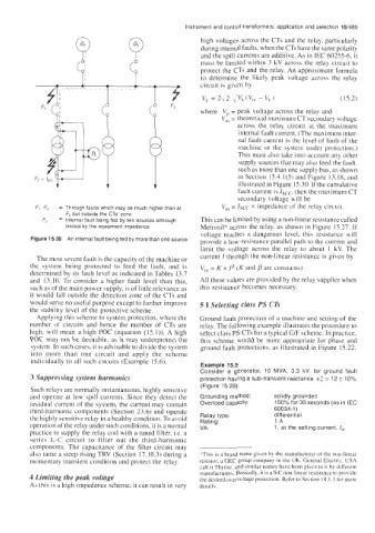
F, F3 - Through faults which may be much higher than at V,, = lscc x impedance of the relay circuit.
F2 but outside the CTs zone
F2 - Internal fault being fed by two sources although This can be limited by using a non-linear resistance called
limited by the equipment impedance Metrosil" across the relay, as shown in Figure 15.27. If
voltage reaches a dangerous level, this resistance will
Figure 15.30 An internal fault being fed by more than one source provide a low-resistance parallel path to the current and
limit the voltage across the relay to about 1 kV. The
The most severe fault is the capacity of the machine or current I through the non-linear resistance is given by
the system being protected to feed the fault, and is V,, = K x Ip (K and p are constants)
determined by its fault level as indicated in Tables 13.7
and 13.10. To consider a higher fault level than this, All these values are provided by the relay supplier when
such as of the main power supply, is of little relevance as this resistance becomes necessary.
it would fall outside the detection zone of the CTs and
would serve no useful purpose except to further improve 5 I Selecting class PS CTs
the stability level of the protective scheme.
Applying this scheme to system protection, where the Ground fault protection of a machine and setting of the
number of circuits and hence the number of CTs are relay. The following example illustrates the procedure to
high. will mean a high POC (equation (15.1)). A high select class PS CTs for a typical G/F scheme. In practice,
POC may not be desirable, as it may underprotect the this scheme would be more appropriate for phase and
system. In such cases, it is advisable to divide the system ground fault protections, as illustrated in Figure 15.22.
into more than one circuit and apply the scheme
individually to all such circuits (Example 15.6).
Example 15.5
Consider a generator, 10 MVA, 3.3 kV, for ground fault
3 Suppressing system harmonics protection having a sub-transient reactance x; = 12 f 10%
(Figure 15.29).
Such relays are normally instantaneous, highly sensitive
and operate at low spill currents. Since they detect the Grounding method: solidly grounded
residual current of the system, the current may contain Overload capacity: 150% for 30 seconds (as in IEC
third-harmonic components (Section 23.6) and operate 60034-1 )
the highly sensitive relay in a healthy condition. To avoid Relay type: differential
Rating:
operation of the relay under such conditions, it is a normal VA: 1A
1, at the setting current, lSt
practice to supply the relay coil with a tuned filter, i.e. a
series L-C circuit to filter out the third-harmonic
components. The capacitance of the filter circuit may
also tame a steep rising TRV (Section 17.10.3) during a *This is a brand name given by the manufacturer of the non-linear
momentary transient condition and protect the relay. resistor. a GEC group company in the UK. General Electric. USA
call it Thyrite, and similar names have been given to it hy different
manufacturers. Basically, it is a Sic non-linear resistance to provide
4 Limiting the peak voltage the desired overvoltage protection. Refer to Section 18.1. I for more
As this is a high-impedance scheme, it can result in very details.