
Page 516 - Industrial Power Engineering and Applications Handbook
P. 516
15/490 Industrial Power Engineering and Applications Handbook
of 0.5 and above and a corresponding VA burden of 5 for
a short-time current of 1 second. If these parameters are
not suitable use the measuring CT with a higher-rated
primary current to meet the requirement.
Similarly, for a protection CT from Table 15.11 choose
an accuracy class of 10P5 with a VA burden of 5 for a
second short-time current. If this does not meet the need,
the protection CT may also have to be selected with a
higher-rated primary current.
15.8 Summary of specifications
of a CT
In Table 15.12 we listed the data, that a user must provide
to a manufacturer to design a CT for a particular
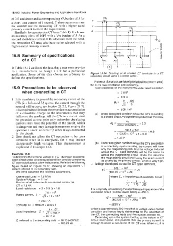
application. Some of the data chosen are arbitrary to Figure 15.34 Shorting of all unused CT terminals in a CT
define the specifications. secondary circuit using a selector switch
For ease of analysis we have ignored (without much error)
the CT's own resistance and reactance.
15.9 Precautions to be observed Total resistance of the instruments under rated condition
when connecting a CT = 7.5/5'
= 0.3 R
It is mandatory to ground the secondary circuit of the 11
CTs (in a balanced 3$ system, the current through the q= -x- 400
neutral will be zero; see Section 21.2.2, Figure 21.7). & 5
It is required to eliminate the error due to accumulation = 508.1 kV
of electrostatic charge on the instruments that may (a) Under energized condition when the CT's secondary
influence the readings. All the CTs in a circuit must is a closed circuit, voltage developed across the relay,
be grounded at one point only otherwise circulating
currents may raise the potential of the circuit, which e; = circuit impedance x 0.3
e*
,
is dangerous and may damage instruments or give the
operator a shock or even trip other relays connected 508.1 x lo3 x 0.3
in the circuit. - (103.23 x lo3 + 1 + 0.3)
One should not allow the CT secondary to be open = 1.48 V
circuited when it is energized, for it may induce
dangerously high voltages. This phenomenon is (b) Under energized condition when the CT's secondary
explained in Example 15.8. is accidentally open circuited, the current will have
only the magnetizing path and the voltage induced
across the CT open terminals will be the same as
Example 15.8 across the magnetizing circuit. Under this situation
To determine the terminal voltage of a CT during an accidental the magnetizing circuit shall carry the same current
open circuit under an energized condition consider a metering as caused by the primary current, which is very high.
CT connected across a few instruments. Refer to the following :. Voltage developed across the CT open terminals,
figure based on Figure 15.17, showing an equivalent CT
circuit referred to its secondary side. = 508.1 x lo3 x Ze
We have assumed the following parameters, (103.23 x lo3 + Ze)
Connected Load = 7.5 MVA [where Z, = Impedance of excitation circuit,]
System Voltage = 11 kV
1
1
Burden of all instruments connected across the 1 - 170 +J60
CT = 7.5 VA Z,
Lead resistance = 2 x 0.5 R = 10 For simplicity, considering the approximate impedance of the
7.5 x 10⁶ excitation circuit (without much error) as J60 R
Rated current, I, =
fix x 103 .. = 508.1 x lo3 x J60
11
= 393.7 A (103.23 x lo3 + J60)
Consider a CT ratio of = 40015 A = J295 V
11 io3 which is approximately 200 times that of voltage under normal
Load impedance Z, = condition and hence highly detrimental for the insulation of
45 x 393.7 the CT, the connecting leads and the human contact etc.
= 16.13 51 Depending upon the system loading at the instant of CT
Z, referred to the secondary side = 16.1 3 (400/5)2 circuit interruption, it is possible that the primary current is
= 103.23 kR enough to cause a saturation of the CT core. When so, it is