
Page 513 - Industrial Power Engineering and Applications Handbook
P. 513
Instrument and control transformers: application and selection 15/487
R Y B
Circuit breaker
characteristics
Under healthy condition
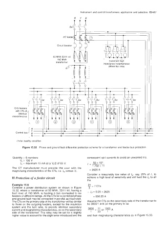
Figure 15.32 Phase and ground fault differential protection scheme for a transformer and feeder bus protection
Quantity = 6 numbers consequent spill currents to avoid an unwanted trip
Vk 2 130 V
50 x lo3
I,,, = maximum 15 mA at a Vk/2 of 65 V. / - -~
1.732xT1
The CT manufacturer must provide the user with the
magnetizing characteristics of the CTs, i.e. I,,, versus V,. = 2625 A
Consider a reasonably low value of Ipf, say, 25% of I,, to
I1 Protection of a feeder circuit achieve a high level of sensitivity and still feed the I,,, to all
the
Example 15.6 1 7 CTs
=
Consider a power distribution system as shown in Figure 3
15 32, where a transformer of 50 MVA, 33/11 kV, having a
fault level of 750 MVA, is feeding a bus connected to six ... I,, = 0.25 x 2625
feeders of different ratings All the CTs for a combined phase = 656.25 A
and ground fault may be connected in parallel as illustrated
The CTs on the primary side of the transformer will be similar Assume the CTs on the secondary side of the transformer to
to those on the outgoing feeders, except for the insulation be 3000/1 and on the primary to be
system and the turn ratio, to provide identical secondary
current and magnetizing characteristics, as on the secondary 3000 11 or 1000 A
side of the transformer The relay may be set for a slightly 1 33 1
higher value to account for the slight error introduced and the and their magnetizing characteristics as in Figure 15.33.