
Page 518 - Industrial Power Engineering and Applications Handbook
P. 518
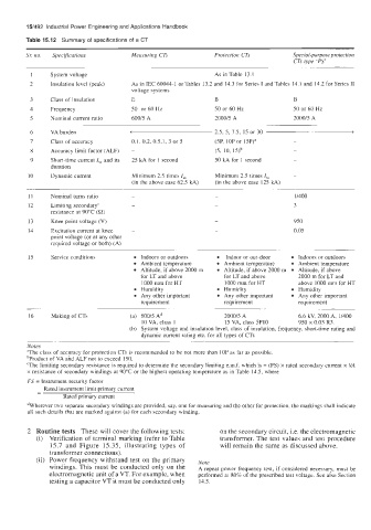
15/492  Industrial  Power Engineering and Applications  Handbook
        Table 15.12  Summary of specifications of a CT

        Sr.  no.   Specifications    Measuring  CTs        Protection CTs        Special-purpose protection
                                                                                 CTs type  ‘PS’
         1     System voltage                               As in Table  13.1
         2     Insulation  level (peak)   As in IEC 60044-1 or Tables 13.2 and  14.3 for Series I and Tables 14.1 and  14.2 for Series I1
                                     voltage systems
         3     Class of insulation   E                      B                    B
         4     Frequency             50  or 60Hz            50 or 60 Hz          SO or 60 Hz
         5     Nominal current ratio   600/5 A              2000/5 A             2000/5 A
         6     VA burden            <                       2.5, 5, 7.5, 15 or 30                >
         7     Class of accuracy     0.1, 0.2, 0.5,1,  3 or 5   (SP,  IOP or  15P)a   -
         8     Accuracy  limit factor (ALF)   -             (5, 10, 15)b         -
         9     Short-time current I,,  and its   25 kA for 1  second   SO kA for 1 second   -
               duration
         10    Dynamic current       Minimum 2.5 times I,,   Minimum  2.5 times I,,   -
                                     (in the above case 62.5 kA)   (in the above case 125 kA)
         11    Nominal turns ratio                                               1/400
         12    Limiting  secondary‘                                              3
               resistance  at 90°C (a)
         13    Knee point voltage (V)                                            950
         14    Excitation  current at knee                                       0.05
               point voltage (or at any other
               required  voltage or both)  (A)
         15    Service conditions      Indoors or outdoors     Indoor or out-door   Indoors or outdoors
                                       Ambient temperature    Ambient temperature   Ambient temperature
                                       Altitude, if above 2000 m   Altitude, if above 2000 m   Altitude, if above
                                       for LT and above       for LT and above    2000 m for LT and
                                        1000 mm for HT        1000 mm for HT      above 1000 mm for HT
                                       Humidity               Humidity            Humidity
                                       Any other important    Any other important   Any other important
                                       requirement            requirement         requirement
         16    Making of CTs           600/5 Ad               2000/5 A            6.6 kV,  2000 A,  1/400
                                        IO VA, class  1       15 VA, class 5P10   950 x 0.05 R3.
                                       System voltage and insulation  level, class of insulation, frequency, short-time rating  and
                                       dynamic current rating etc. for all types of CTs
        Notes
        “The class of accuracy for protection  CTs is recommended  to be not more than  IOP as far as possible.
        bProduct of VA  ahd ALF not to exceed  150.
        ‘The  limiting secondary resistance  is required to determine the secondary limiting e.m.f. which is = (FS) x rated secondary current x VA
        x resistance of  secondary windings at 90°C or the highest operating  temperature  as in Table  14.5, where
        FS  = Instrument security factor
             Rated instrument limit orimarv current
                  Rated primary current
        dWherever two separate secondary windings are provided, say, one for measuring and the other for protection,  the markings shall  indicate
        all such details that are marked  against (a) for each secondary  winding.

        2  Routine tests  These will cover the following tests:   on the secondary circuit, i.e. the electromagnetic
           (i)   Verification  of terminal marking (refer to Table   transformer. The test values and test procedure
               15.7  and  Figure  15.35,  illustrating  types  of   will remain the same as discussed above.
              transformer connections).
           (ii)  Power frequency withstand  test on the primary   Note
              windings.  This must  be conducted Only  On  the   A repeat  power  frequency  test,  if  considered necessary,  must be
              electromagnetic unit of a VT. For example, when   performed at 80% of the prescribed  test voltage.  See also Section
              testing a capacitor VT it must be conducted only   14.5.