
Page 520 - Industrial Power Engineering and Applications Handbook
P. 520
15/494 Industrial Power Engineering and Applications Handbook
(iii) Temperature rise test
(iv) Verification of dielectric properties on the primary
windings to check the insulation level as in Tables 1 1
13.2 and 14.3 for series I and Tables 14.1 and Sl s2
14.2 for series I1 voltage systems. (1) Single ratio CT (2) CT with an intermediate
(a) Power frequency voltage withstand or HV tapping on the secondary winding
test. C. C9
(b) Impulse voltage withstand or lightning impulse
test for system voltages 2.4 kV and above.
Since a CT is associated with a switchgear, either
with its assembly or the switchyard, the above
four tests are almost the same as those for a
switchgear assembly and as discussed in Chapter s1 s2 1s1 Is, 2% 2s2
14. The test requirements and procedure are also (3) CT with a primary winding (4) CT with two secondaty windings,
similar. in 2 sections which may be each with its own magnetic core.
(v) Wet test for outdoor type transformer: This test connected in series or
parallel
is similar to that for a VT and as discussed in
Section 15.10.1(1). Figure 15.36 A CT wound in different combinations
(vi) Verification of accuracy: the test results obtained
must comply with the values of Tables 15.8 and
15.9 for a measuring and a protection CT
respectively. achieve an appreciable deflection of the voltmeter
2 Routine Tests These will cover the following tests: needle.
(i) (a) Verification of terminal marking (ii) Power frequency withstand test on secondary
Refer to Figure 15.36, illustrating types of windings
transformer connections. The secondary windings should be capable of
(b) To check the polarity of a CT It is imperative withstanding a rated power frequency, short-
that the terminals of a CT are wired with duration withstand voltage of 3 kV for 1 minute.
correct polarity, with reference to the primary (iii) Power frequency withstand test between
in each phase. A reversal in any phase will sections
lead to incorrect meter readings, in metering This test is applicable when the CT's primary
CTs and erratic signals to the protective relays and secondary windings have two or more
in protection CTs. Although CTs are marked sections. Then the section in between will be
with polarities by their manufacturers, such capable of withstanding a similar voltage as noted
as PI P2 for primary and SI S2 for secondary in item (ii) above.
(Figure 15.36) it is possible, that by human (iv) Inter-turn overvoltage test
error at the time of fitting the CTs, care is not This test is performed to check the suitability of
taken to maintain the same polarity in all the the inter-turn insulation to withstand the high
three phases, or their connections are made
inadvertently, without ascertaining their Voltmeter
correct polarity. It is also possible that on a or
reconnection, such as at site, while Ammeter
reassembling the modules of a switchgear or
a controlgear assembly, such an omission is
made. It is therefore advisable that the polarity
of the CTs be ascertained at site before
commissioning the equipment, such as a
switchgear or a controlgear assembly or a
switchyard utilizing a few CTs. Primary Secondary
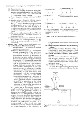
D.C. voltage test to ascertain the polarity: A terminals
simple procedure to ascertain this is indicated in l~l~l~+
Figure 15.37. A low reading d.c. voltmeter is Pl pz D.C. source
connected across the CT secondary windings and (6V-12V)
a battery of 6-12 V through a switch across the
primary. On closing the switch, the meter needle
will give a momentary flicker. If the polarity is
correct, the flicker will be positive on connection
and negative on disconnection. For HT CTs,
mounted on transformer bushings, it is -0 Switch
recommended to short-circuit the main
transformer secondary (LV) windings to reduce Figure 15.37 Circuit to check the polarity of a bar primary CT
the overall impedance of the transformer to at site