
Page 519 - Industrial Power Engineering and Applications Handbook
P. 519
Instrument and control transformers: application and selection 151493
(iii) Power frequency withstand test on the secondary (c) D.C. discharge test.
windings. This must also be conducted only on (d) Impulse voltage withstand test.
the electromagnetic unit of a VT, as noted above, (e) Partial discharge (ionization) test.
at 2 kV for 1 minute, similar to the control and 2 Temperature rise test.
auxiliary circuit dielectric test (Table 14.3). 3 Impulse voltage withstand test.
(iv) Verification of accuracy: as under type tests above. 4 Ferro-resonance test.
Field tests Power frequency withstand test on the 5 Transient response test.
primary windings (for un-grounded VTs). The value 6 Verification of accuracy.
of the test voltage and the test procedure, is almost
the same as that for a switchgear assembly (Section Routine tests
14.5).
Additional tests on a capacitor VT The tests 1 Tests on capacitors
discussed above refer generally to the electromagnetic (a) Capacitance and tangent of the loss angle (tan 6)
unit only. To test the whole VT, the following tests (b) Power frequency dry withstand test
are recommended. For the test procedure and results (c) Sealing test
refer to IEC 601886. 2 Verification of terminal marking
3 Power frequency withstand test on the secondary circuit
4 Verification of accuracy
Type tests
15.10.2 Current transformers
I Tests on capacitors
(a) Self-resonating frequency test - applicable only 1 Type tests These will cover the following tests:
to carrier coupling capacitors. (i) Short-time current (Isc) test
(b) Power frequency wet withstand test on outdoor (ii) Momentary peak or dynamic current test. (This
capacitors. must be conducted at a minimum of 2.5 /sc)
R YorN
T T
r7
1R' 1Y'or IN' mr7
R' Y'or N r7 R' N R' N'
(1) Single phase VT (5) Single phase residual VT
2R' 2Y'or 2N
(2) Single phase VT with two
secondary windings
2"
R Y B N
t t t t
i i PT B A
'1'1-1 Y Y J B' TN Y
B B t i
(3) 3-phase VT
(4) 3-phase VT with two (6) 3-phase residual VT Y"
secondary windings
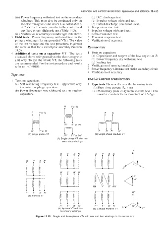
Figure 15.35 Single and three-phase VTs with one and two windings in the secondary