
Page 506 - Industrial Power Engineering and Applications Handbook
P. 506
15/480 Industrial Power Engineering and Applications Handbook
Similarly, the balance is disturbed in the differential vary with the CT secondary voltage;
scheme on a fault of any type and a spill current, which refer to Figure 15.19)
is the difference between the currents drawn by the two I,,, I,. = I, = circulating currents
sets of CTs, flows through the relay. Since the scheme Ire = spill or differential current through
functions on the principle of balance of currents, it is the relay
imperative that the two sets of CT parameters, such as Vfl, Vfr = V, = CT secondary voltages under rated
their ratio, secondary resistance and the magnetizing conditions (these relays are defined
current, should be identical, except for the permissible by both the current and the voltage
tolerances as discussed in Section 15.10.2. The secondary settings)
lead resistances, from the CTs to the relay terminals, R, = resistance of the relay coil
should also be the same, otherwise, spill currents may VA whcrc VA is the burden of the
flow through the relay, even under healthy condition and = ~ 13
cause an unwanted trip, or require a higher minimum relay. This may be specified in terms
setting of the relay. A higher setting of the relay may of its current rating 1 A or 5 A or
jeopardize its sensitivity to detect minor faults. Since it setting current Ist. Considering this
is not practical to produce all CTs to be identical, small to be 1 VArelay at a setting of 0.05 A,
spill currents under healthy condition are likely and the
minimum relay setting, IEt, must account for this. Below R,=-- -400Q
we consider three different cases to explain the principle (0.05)’
of circulating currents, along with the procedure, to select I,, = relay setting
the CTs and carry out the relay setting. R12 = R, = maximum resistance of the
connecting leads from the CT
Equivalent circuit diagram and selection of terminals to the relay terminals. For
calculating this, for an estimated
class PS CTs length and size, refer to cable data
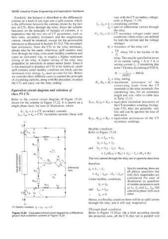
Refer to the control circuit diagram of Figure 15.24, in Table 13.15
drawn for the scheme in Figure 15.22. It is drawn on a XCT,, XCT2 = XCT = equivalent excitation reactances of
single-phase basis for ease of illustration, where the CT secondary windings. In ring-
type CTs, they are generally very
Ifl, Ir, = If = CT secondary currents low and can be ignored for ease of
=
I,,, lm2 I, = CTs’ excitation currents (these will derivation
RCTI, RCTZ = RCT = equivalent resistances of the CT
secondary windings
Ll
c
The two current through the relay are in opposite directions
therefore
Differential Strictly speaking, these are
relay Ire = IC2 - IC, all phasor quantities but
= - Im2) - (If, - I~z) only their magnitudes are
Under healthy conditions considered for ease of
illustration, as quantities
If1 = If2 of similar parameters such
as If,, If2 and I,,,,, I,, fall
and I,, =Irn2 almost in phase with each
:. I,, = 0 other.
Hence, in a healthy condition there will be no spill current
through the relay and it will stay inoperative.
L2
(1) Healthy condition, I,, = lCz - I,, = 0
Through-fault condition
Figure 15.24 Equivalent control circuit diagram for a differential Refer to Figure 15.25(a). On a fault occurring outside
ground fault protection scheme of Figure 15.22 the protected zone, all the CTs that fall in parallel will