
Page 502 - Industrial Power Engineering and Applications Handbook
P. 502
15/476 Industrial Power Engineering and Applications Handbook
-
E
I -
a, Dl
P
+ VA, +
Main CT Interposing CT
.? .- (VAM) ( 4)
C
I (a) Schematic diagram
.-
::
Excitation current (I,,,) -
u
Figure 15.19 Knee point of the excitation characteristic of a
current transformer
must be as in Table 15.8, according to IEC 60044-1,
when the secondary burden is a minimum 25% of its + I
rated'burden for CTs up to class 1 and 50% for CTs of Main CT
classes 3 and 5. (b) Equivalent control circuit diagram
The recommended class of accuracy will depend upon
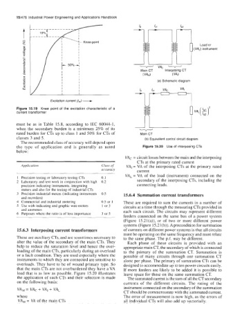
the type of application and is generally as noted Figure 15.20 Use of interposing CTs
below:
VAc = circuit losses between the main and the interposing
CTs at the primary rated current
Application Class of VAI = VA of the interposing CTs at the primary rated
accuracy current
VAL = VA of the load (instrument) connected on the
1 Precision testing or laboratory testing CTs 0.1
2 Laboratory and test work in conjunction with high 0.2 secondary of the interposing CTs, including the
precision indicating instruments, integrating connecting leads.
meters and also for the testing of industrial CTs
3 Precision industrial meters (indicating instruments 0.5 15.6.4 Summation current transformers
and recorders)
4 Commercial and industrial metering 0.5 or 1 These are required to sum the currents in a number of
5 Use with indicating and graphic watt-meters 1 or 3 circuits at a time through the measuring CTs provided in
and ammeters each such circuit. The circuits may represent different
6 Purposes where the ratio is of less importance 3 or 5
feeders connected on the same bus of a power system
(Figure 15.21(a)), or of two or more different power
systems (Figure 15.2 1 (b)). A precondition for summation
15.6.3 Interposing current transformers of currents on different power systems is that all circuits
must be operating on the same frequency and must relate
These are auxiliary CTs, and are sometimes necessary to to the same phase. The p.f. may be different.
alter the value of the secondary of the main CTs. They Each phase of these circuits is provided with an
help to reduce the saturation level and hence the over- appropriate main CT, the secondary of which is connected
loading of the main CTs, particularly during an overload to the primary of the summation CT. Summation is
or a fault condition. They are used especially where the possible of many circuits through one summation CT
instruments to which they are connected are sensitive to alone per phase. The primary of summation CTs can be
overloads. They have to be of wound primary type. So designed to accommodate up to ten power circuits easily.
that the main CTs are not overburdened they have a VA If more feeders are likely to be added it is possible to
load that is as low as possible. Figure 15.20 illustrates leave space for these on the same summation CT.
the application of such CTs and their selection is made The summated current is the sum of all the CT secondaq
on the following basis: currents of the different circuits. The rating of the
VAI, = VAc + VAI + VAL instrument connected on the secondary of the summation
CT should be commensurate with the summated current.
where The error of measurement is now high, as the errors of
VA, = VA of the main CTs all individual CTs will also add up vectorially.