
Page 500 - Industrial Power Engineering and Applications Handbook
P. 500
15/474 Industrial Power Engineering and Applications Handbook
at least sufficient to operate the relay. At a 40% setting,
for instance, the CT must have a VA of (U0.4 I)2 or
6.25 times the VA of the relay and at a setting of 20%,
(U0.2 I)’ or 25 times of the relay. Therefore when the
relay setting is low this must be borne in mind and a
CT of a higher VA burden be chosen. Such a
consideration, however, is more pertinent in the case
of electro-magnetic relays that have a high VA level
than in electrostatic (electronic) relays that have a
near negligible VA level at only around 0.005 VA.
Where three CTs for unrestricted or four CTs for
restricted ground fault or combined OK and G/F
protections are employed in the protective circuit, the
VA burden of the relay is shared by all the CTs in parallel
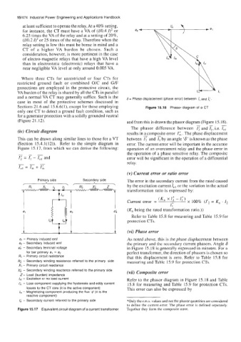
and a normal VA CT may generally suffice. Such is the 6 = Phase displacement (phase error) between i, and I;.
case in most of the protective schemes discussed in
Sections 21.6 and 15.6.6(1), except for those employing Figure 15.18 Phasor diagram of a CT
only one CT to detect a ground fault condition, such as
for a generator protection with a solidly grounded neutral
(Figure 21.12). and from this is drawn the phasor diagram (Figure 15.18).
-
The phasor difference between zand I,, i.e.
(iv) Circuit diagram results in a composite error I;. The phase displacement
This can be drawn along similar lines to those for a VT between and 7; by an angle ‘6’ is known as the phase
(Section 15.4.1(12)). Refer to the simple diagram in error. The current error will be important in the accurate
Figure 15.17, from which we can derive the following: operation of an overcurrent relay and the phase error in
the operation of a phase sensitive relay. The composite
E= 7;- Land error will be significant in the operation of a differential
--- relay.
I,, = I, 4- I;
(v) Current error or ratio error
Primary side Secondary side . The error in the secondary current from the rated caused
A .., A
r
R; X; Z by the excitation current I,, or the variation in the actual
transformation ratio is expressed by:
(K, xr; -1;)
Current error = x 100% (1’2 = K, . 12
l I;
e; (K, being the rated transformation ratio.))
Refer to Table 15.8 for measuring and Table 15.9 for
protection CTs.
t t t (vi) Phase error
e, - Primary induced emf As noted above, this is the phase displacement between
4 - Secondary induced emf the primary and the secondary current phasors. Angle 6
e; - Secondary terminal voltage in Figure 15.18 is generally expressed in minutes. For a
for bar primary e, = e, perfect transformer, the direction of phasors is chosen so
R, - Primary circuit resistance that this displacement is zero. Refer to Table 15.8 for
R; - Secondary winding resistance referred to the primary side measuring and Tablc 15.9 for protection CTs.
X, - Primary circuit reactance
X; - Secondary winding reactance referred to the primary side (vii) Composite error
Z- Load (burden) impedance
/,,( - Excitation or no load current Refer to the phasor diagram in Figure 15.18 and Table
/& - Loss component supplying the hysteresis and eddy current 15.8 for measuring and Table 15.9 for protection CTs.
losses to the CT core (it is the active component) This error can also be expressed by
/m - Magnetizing component producing the flux ‘4’ (it is the
reactive component)
1; - Secondary current referred to the primary side *Only the r.m.s. values and not the phasor quantities are considered
to define the current error. The phase error is defined separately.
Figure 15.17 Equivalent circuit diagram of a current transformer Together they form the composite error.