
Page 499 - Industrial Power Engineering and Applications Handbook
P. 499
istrument and control transformers: application and selection 15/473
VA = 52 x [l + 3.93 x 10" (90-20)]
1000
= 2.42 VA (for details refer to Table 14.4)
Computing the VA burden
1 The VA values of some of the devices used in the
circuit may be available at a different current rating
from the actual rated secondary current (1 or 5 A)
chosen for the CT circuit. To compute the VA burden
of a circuit when selecting the correct VA level of a
CT, the VA values of all the devices not corresponding
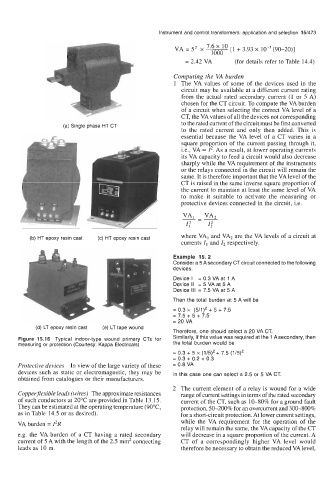
(a) Single phase HT CT to the rated current of the circuit must be first converted
to the rated current and only then added. This is
essential because the VA level of a CT varies in a
square proportion of the current passing through it,
Le., VA = 12. As a result, at lower operating currents
its VA capacity to feed a circuit would also decrease
sharply while the VA requirement of the instruments
or the relays connected in the circuit will remain the
same. It is therefore important that the VA level of the
CT is raised in the same inverse square proportion of
the current to maintain at least the same level of VA
to make it suitable to activate the measuring or
protective devices connected in the circuit, i.e.
(b) HT epoxy resin cast (c) HT epoxy resin cast where VA, and VA2 are the VA levels of a circuit at
currents I, and Z2 respectively.
Example 15. 2
Consider a 5 A secondary CT circuit connected to the following
devices:
Device I = 0.3 VA at 1 A
Device II = 5 VA at 5 A
Device 111 = 7.5 VA at 5 A
Then the total burden at 5 A will be
= 0.3 x (5/1)' + 5 + 7.5
= 7.5 + 5 + 7.5
= 20 VA
(d) LT epoxy resin cast (e) LT tape wound
Therefore, one should select a 20 VA CT.
Figure 15.16 Typical indoor-type wound primary CTs for Similarly, if this value was required at the 1 A secondary, then
measuring or protection (Courtesy: Kappa Electricals) the total burden would be
= 0.3 + 5 x (1/5)'+ 7.5 (1/5)'
= 0.3 + 0.2 + 0.3
Protective devices In view of the large variety of these = 0.8 VA
devices such as static or electromagnetic, they may be In this case one can select a 2.5 or 5 VA CT.
obtained from catalogues or their manufacturers.
2 The current element of a relay is wound for a wide
Copperflexible leads (wires) The approximate resistances range of current settings in terms of the rated secondary
of such conductors at 20°C are provided in Table 13.15. current of the CT, such as 1040% for a ground fault
They can be estimated at the operating temperature (9OoC, protection, 50-200% for an overcurrent and 300400%
as in Table 14.5 or as desired). for a short-circuit protection. At lower current settings,
VA burden = 12R while the VA requirement for the operation of the
relay will remain the same, the VA capacity of the CT
e.g. the VA burden of a CT having a rated secondary will decrease in a square proportion of the current. A
current of 5 A with the length of the 2.5 mm2 connecting CT of a correspondingly higher VA level would
leads as 10 m. therefore be necessary to obtain the reduced VA level,