
Page 491 - Industrial Power Engineering and Applications Handbook
P. 491
Instrument and control transformers: application and selection 15/465
Primary voltage
terminal
EHV line
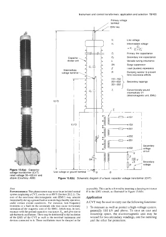
Line voltage
Intermediate voltage
c1
= ve.
CI Primary line capacitance
Capacitor c, Secondary line capacitance
divider unit L Variable tuning inductance
SA Surge suppressor
Intermediate 4 L1 T h Z Load (burden) impedance
voltage terminal 5 I R Damping resistor to prevent
ferro-resonance effects
1s1-1s2
2s1-2s2 Secondary tappings
3S1-352
Tr Conventionally wound
intermediate VT
(electromagnetic unit, EMU)
v,/d3
3
3 Secondary
i1 1 Secondary
voltage
Figure 15.6(a) Capacitor R voltage
voltage transformer (CVT) 'G G
rated voltage 36-420 kV and
above (Courtesy: ABB) Figure 15.6(b) Schematic diagram of a basic capacitor voltage transformer (CVT)
Note as possible. This can be achieved by inserting a damping resistance
Ferroresonance: This phenomenon may occur in an isolated neutral R in the EMU circuit, as illustrated in Figure 15.6(b).
system employing a CVT, similar to an RVT (Section 20.2.1). The
core of the non-linear electromagnetic unit (EMU) may saturate Application
momentarily during a ground fault or even during a healthy operation, A CVT may be used to carry Out the functions:
under certain circuit conditions. For instance, low-frequency
transients or a fault on the secondary side may cause momentary 1 To measure as well as protect a high-voltage system,
saturation of the magnetic core of the EMU, which may, in turn, generally 110 kV and above. To save on cost and
resonate with the ground capacitive reactances Xcs and give rise to
sub-harmonic oscillations. These may be detrimental to the insulation mounting space, the electromagnetic unit may be
of the EMU of the CVT as well as the terminal instrument and wound for two secondary windings, one for metering
devices connected to it. These oscillations must be damped as far and the other for protection.