
Page 493 - Industrial Power Engineering and Applications Handbook
P. 493
Instrument and control transformers: application and selection 15/467
maximum switching inrush VA burden of the various consuming power. It is advisable to add the VA burdens
auxiliary devices connected in the switching circuit vectorially rather than algebraically. Since a control
such as contactors, timers and indicating lights. Unless transformer may feed more auxiliary components and
specified, the short-time VA burden of the transformer devices consuming power compared to an instrument
will be a minimum of eight times its rating at 0.5 p.f. VT, the VA rating of such transformers is generally higher
lagging. It can be expressed in terms of VA versus than of an instrument, metering or protection VT.
cos 4 and drawn in the form of an inrush curve, for Algebraic summation will lead to a higher VA
easy selection of a transformer rating (Figure 15. IO). requirement than necessary. The transformer should not
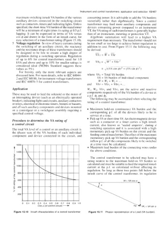
5 Voltage regulation In view of heavy currents during be too small or too large to achieve better regulation in
the switching of an auxiliary circuit, the reactance addition to cost. From Figure 15.11 the following may
and the resistance drops of these transformers should be derived:
be designed to be low to ensure a high degree of
regulation during a switching operation. Regulation VAr=W+VAr
of up to 6% for control transformers rated for 1.0
kVA and above and up to 10% for smaller ratings is or VAT = ,/W2 + VAr’
considered ideal (NEMA Standard suggests these
values as 5%).
For brevity, only the more relevant aspects are
discussed here. For more details, refer to IEC 60044- where VAT = Total VA burden
2 and IEC 601 86, for instrument voltage transformers VA = VA burden of individual component
+
and IEC 60076-3 for control transformers. w= w, w, + ...
and VAr = VAr, + VAr2 +. , .
Application W,, W,, VAr, and VAr, are the active and reactive
components respectively of the VA burden of a device at
These may be used to feed the solenoid or the motor of a p.f. 4, and &.
an interrupting device (such as an electrically operated The following may be ascertained when selecting the
breaker), indicating lights and circuits, auxiliary contactors rating of a control transformer:
or relays, electrical or electronic timers, hooters or buzzers,
and all such auxiliary components and devices mounted
on a controlgear or a switchgear assembly requiring a Maximum hold-on (continuous) VA burden and the
specified control voltage. corresponding p.f. of all the devices likely to be in
service at a time.
Pick-up VA or short-time VA: An electromagnetic device
Procedure to determine the VA rating of such as a contactor or a timer carries a high inrush
a control circuit current, also known as ‘sealed amperes’, during a
The total VA level of a control or an auxiliary circuit is switching operation and it is associated with a high
the phasor sum of the VA burdens of each individual momentary pick-up VA burden on the circuit and the
component and device connected in the circuit, and feeding control transformer. The effect of the maximum
momentary pick-up VA burden and the corresponding
inflow p.f. of all the components likely to bc switched
at a time must be calculated.
Maximum lead burden of the connecting wires under
the above conditions.
The control transformer to be selected may have a
rating nearest to the maximum hold-on VA burden so
calculated and must be suitable to feed the required inrush
current at the p.f. so calculated without affecting its
regulation. So long as these two points fall below the
inrush curve of the control transformer, its regulation
Cos I$ (of control circuit) -
0 01 02 03 04 05 06 07 08 09 10
Figure 15.10 Inrush characteristics of a control transformer Figure 15.11 Phasor representation of a Load (VA burden).